


20-40
Cisco Prime Network 4.0 User Guide
OL-29343-01
Chapter 20 Monitoring MToP Services
Network Clock Service Overview
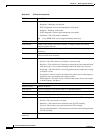
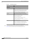
Sync Interval (log
mean value)
Interval for sending PTP synchronization messages:
• 4—1 packet every 16 seconds.
• 3—1 packet every 8 seconds.
• 2—1 packet every 4 seconds.
• 1—1 packet every 2 seconds.
• 0—1 packet every second.
• -1—1 packet every 1/2 second, or 2 packets per second.
• -2—1 packet every 1/4 second, or 4 packets per second.
• -3—1 packet every 1/8 second, or 8 packets per second.
• -4—1 packet every 1/16 seconds, or 16 packets per second.
• -5—1 packet every 1/32 seconds, or 32 packets per second.
• -6—1 packet every 1/64 seconds, or 64 packets per second.
Sync Limit
(nanoseconds)
Maximum clock offset value, in nanoseconds, before PTP attempts to
resynchronize.
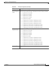
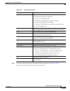
Interface Physical interface identifier, hyperlinked to the routing information for the
interface.
PTP Master Mode For an interface defined as a master device, the mode used for PTP clocking:
• Not Set—The master mode is not used.
• Multicast—The interface uses multicast mode for PTP clocking.
• Unicast—The interface uses unicast mode for PTP clocking. This mode
allows a single destination.
• Unicast with Negotiation—The interface uses unicast mode with negotiation
for PTP clocking. This mode allows up to 128 destinations.
Clock Destination
Addresses
IP addresses of the clock destinations. This field contains IP addresses only when
Master mode is enabled.
Domain Clocking domain.
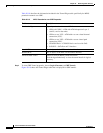
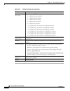
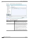
Table 20-21 PTP Service Properties (continued)
Field Description