


3-21
Cisco Prime Network 4.0 User Guide
OL-29343-01
Chapter 3 Viewing and Managing NE Properties
Viewing the Physical Properties of a Device
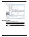
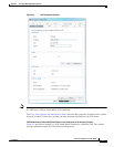
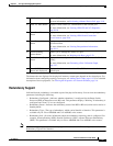
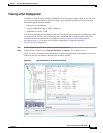
The buttons that are displayed in the physical inventory content pane depend on the selected port. For
information about configuring topology from a port, see Adding Static Links, page 6-15. For a detailed
description of device properties, see Viewing the Properties of a Network Element, page 3-6.
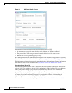
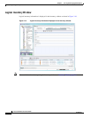
Redundancy Support
In Prime Network, redundancy is modeled as part of the physical inventory. You can view the redundancy
parameters including the following:
• Redundancy Configured—Indicates whether redundancy is configured for the Route Switch
Processor (RSP) or Route Processor (RP) card. This parameter displays “Working” if redundancy is
configured and “None” if it is not configured.
• Redundancy Status—Indicates the redundancy status of the RSP or RP card, which can be Active or
Standby Mode.
• Redundancy Type—The type of redundancy, which can be Stateful or Stateless. This parameter is
available only for Cisco ASR9000 and Cisco ASR903 series routers.
• Redundancy Info—Provides information about the redundancy technology that is configured. For
example, Nonstop Routing (NSR), Stateful Switchover (SSO), or Route Processor Redundancy
(RPR). This parameter is available only for Cisco ASR9000 and Cisco ASR903 series routers.
Note If SSO is configured, then the Redundancy type will be Stateful. If RPR is configured, then the
Redundancy Type will be Stateless.
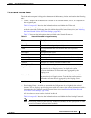
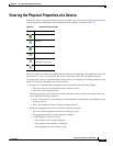
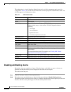
1 Poll Now button Poll the VNE and update the information as needed.
For more information, see Performing a Manual Device Poll, page 3-18.
2 Show VC Table button Displays virtual circuit (VC) information for the selected port.
For more information, see Viewing ATM VPI and VCI Properties,
page 20-10.
3 Show Cross Connect
button
Displays cross-connect information for incoming and outgoing ports.
For more information, see Viewing ATM Virtual Connection
Cross-Connects, page 20-6.
4 Show Encapsulation
button
Displays encapsulation information for incoming and outgoing traffic for
the selected item.
For more information, see Viewing Encapsulation Information,
page 20-11.
5 Disable Sending
Alarms button
Enables you to manage the alarms on a port.
For more information, see Working with Ports, page 3-23.
6 Port Utilization Graph
button
Displays the selected port traffic statistics: Rx/Tx Rate and Rx/Tx Rate
History.
For more information, see Generating a Port Utilization Graph,
page 3-27.
— Show DLCI Table
button (not displayed)
Displays data-link connection identifier (DCLI) information for the
selected port.