


12-23
Cisco Prime Network 4.0 User Guide
OL-29343-01
Chapter 12 Monitoring Carrier Ethernet Services
Working with Ethernet Link Aggregation Groups
Working with Ethernet Link Aggregation Groups
Ethernet link aggregation groups (LAGs) provide the ability to treat multiple switch ports as one switch
port. The port groups act as a single logical port for high-bandwidth connections between two network
elements. A single link aggregation group balances the traffic load across the links in the channel.
LAG links are discovered automatically for devices that support LAG technology and use VNEs that
model Link Aggregation Control Protocol (LACP) attributes.
You can create static links between Ethernet LAGs by choosing a LAG and the desired port channel for
the A or Z side as described in Adding Static Links, page 6-15.
If a physical link within the link aggregation group fails, the following actions occur:
• Traffic that was previously carried over the failed link is moved to the remaining links.
Most protocols operate over single ports or aggregated switch ports and do not recognize the
physical ports within the port group.
• An aggregation service alarm is generated.
The aggregation service alarm indicates the percentage of links within the aggregation that have
failed. For example, if an Ethernet link aggregation group contains four Ethernet links and one fails,
the aggregation service alarm indicates that 25% of the links are down.
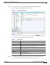
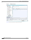
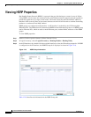
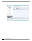
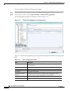
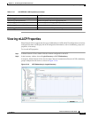
Viewing Ethernet LAG Properties
Note Cisco CRS devices must be configured to receive SNMP traps in order to view Ethernet LAG properties.
For more information on required SNMP settings, see the Cisco Prime Network4.0 Administrator Guide.
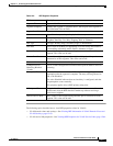
Hello Time Current hello time (in seconds)
Port Active Whether or not the port is active: True or False.
Instances Table
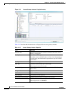
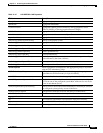
Instance ID Access gateway instance identifier.
VLAN IDs VLAN identifiers.
Cost Path cost for this instance.
Bridge Priority Priority associated with current bridge.
Root Bridge Priority Priority associated with the root bridge.
Root Bridge Address Address of the root bridge.
Port Priority Priority of the interface for this instance.
Topology Changes Number of times the topology has changed for this instance.
Access GW External Cost External root cost of this instance.
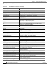
Table 12-12 Access Gateway Instance Properties (continued)
Field Description