


11-34
Cisco Prime Network 4.0 User Guide
OL-29343-01
Chapter 11 Using Cisco PathTracer to Diagnose Problems
Using Cisco PathTracer in MPLS Networks
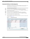
Layer 2 and Layer 3 path trace information is displayed in the Cisco PathTracer details window when a
path is traced over MPLS TE tunnels. To view Layer 2 path information, choose the Layer 2 tab and then
View > Show All. The path information is displayed in the active tab.
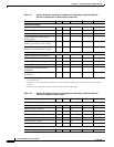
Table 11-15 describes the Layer 2 properties that can be displayed in the Layer 2 tab specifically for
MPLS TE tunnels.
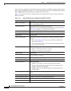
Table 11-15 Cisco PathTracer Layer 2 Properties for MPLS TE Tunnels
Field Description
MPLS TE Properties MPLS TE data set in an MPLS interface, primarily bandwidth allocation
levels and signaling protocol.
Tunnel Oper Status Operational status of the tunnel: Up or Down.
If this value is Up, the Tunnel Admin Status must also be Up. See Tunnel
Admin Status properties for additional information.
Tunnel Bandwidth Kbps Configured bandwidth (in Kb/s) for the tunnel.
Tunnel Description Description of the tunnel.
Tunnel Name Interface name.
Tunnel Admin Status Administrative status of the tunnel (Up or Down) with the following
caveats:
• If the Tunnel Oper Status value is Up, the Tunnel Admin Status
value must also be Up.
• If the Tunnel Admin Status value is Down, the Tunnel Oper Status
value must also be Down.
Tunnel Lockdown Whether or not the tunnel can be rerouted:
• Enabled—The tunnel cannot be rerouted.
• Disabled—The tunnel can be rerouted.
Tunnel LSP ID LSP identifier.
Tunnel Auto Route Whether or not destinations behind the tunnel are routed through the
tunnel: Enabled or disabled.
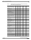
Tunnel Hold Priority Tunnel priority after path setup.
Tunnel Setup Priority Tunnel priority upon path setup.
Tunnel Path Option Tunnel path option:
• Dynamic—The tunnel is routed along the ordinary routing
decisions after taking into account the tunnel constraints such as
attributes, priority, and bandwidth.
• Explicit—The route is explicitly mapped with the included and
excluded links.
Tunnel Out Label TE tunnel MPLS label distinguishing the LSP selection in the adjacent
device.
Tunnel Affinity Tunnel’s preferential bits for specific links.
Tunnel Destination Address IP address of the device in which the tunnel ends.
Tunnel Peak Rate Kbps Peak flow specification (in Kb/s) for this tunnel.
Tunnel Out Interface Interface through which the tunnel exits the device.