


Send documentation comments to mdsfeedback-doc@cisco.com.
19-14
Cisco MDS 9000 Family Fabric Manager Configuration Guide
OL-6965-03, Cisco MDS SAN-OS Release 2.x
Chapter 19 FCIP Configuration
Configuring Advanced FCIP Interfaces
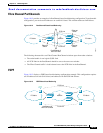
You can configure the required mode for initiating an IP connection. By default, active mode is enabled
to actively attempt an IP connection. If you enable the passive mode, the switch does not initiate a TCP
connection and merely waits for the peer to connect to it. Ensure that both ends of the FCIP link are not
configured as passive mode. If both ends are configured as passive, the connection is not initiated.
You can specify the number of TCP connections from a FCIP link. By default, the switch tries two TCP
connections for each FCIP link. You can configure one or two TCP connections. For example, the Cisco
PA-FC-1G Fibre Channel port adapter, which has only one TCP connection, interoperates with any
switch in the Cisco MDS 9000 Family. One TCP connection is within the specified limit. If the peer
initiates one TCP connection, and your MDS switch is configured for two TCP connections, then the
software handles it gracefully and moves on with just one connection.
You can instruct the switch to discard packets that are outside the specified time for this FCIP link. By
default, this option is disabled in all switches in the Cisco MDS 9000 Family. This option specifies the
time range within which packets can be accepted. If the packet arrived within the range specified by this
option, the packet is accepted. Otherwise, it is dropped. By default if a packet arrives within a 1000
millisecond interval (+ or -1000 ms), that packet is accepted. Use the time-stamp option to enable or
disable FCIP timestamps on a packet.
Note If the time-stamp option is enabled, be sure to configure NTP on both switches. Refer to the Cisco MDS
9000 Family Configuration Guide for information on NTP.
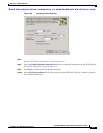
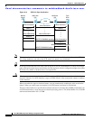
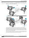
To assign the peer information based on the IP address, port number, or profile ID, follow these steps:
Step 1 From Fabric Manager, choose ISLs > FCIP from the Physical Attributes pane. You see the FCIP profiles
and links in the Information pane.
From Device manager, choose IP > FCIP. You see the FCIP dialog box.
Step 2 Click the Tunnels tab. You see the FCIP link information.
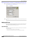
Step 3 Click the Create Row icon in Fabric Manager or the Create button in Device Manager. You see the
FCIP Tunnels dialog box.
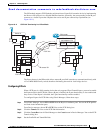
Step 4 Set the ProfileID and TunnelID fields.
Step 5 Set the RemoteIPAddress and RemoteTCPPort fields for the peer IP address you are configuring.
Step 6 Check the PassiveMode check box if you do not want this end of the link to initiate a TCP connection.
Step 7 Optionally set the NumTCPCon field to the number of TCP connections from this FCIP link.
Step 8 Optionally, check the Enable check box in the Time Stamp section and set the Tolerance field.
Step 9 Optionally set the other fields in this dialog box and click Create to create this FCIP link.
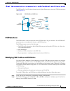
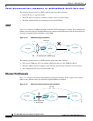
Special Frames
You can alternatively establish an FCIP link with a peer using an optional protocol called special frames.
When special frames are enabled, the peer IP address (and optionally the port or the profile ID) only
needs to be configured on one end of the link. Once the connection is established, a special frame is
exchanged to discover and authenticate the link.
By default, the special frame feature is disabled.