


Send documentation comments to mdsfeedback-doc@cisco.com.
15-3
Cisco MDS 9000 Family Fabric Manager Configuration Guide
OL-6965-03, Cisco MDS SAN-OS Release 2.x
Chapter 15 Zone Configuration
Using the Zone Configuration Tool
Caution You must only configure pWWN-type zoning on an MDS switch running Cisco SAN-OS if there is a
Cisco MDS 9020 switch running FabricWare in the same fabric to avoid ISL isolation. It is important to
remove all non-pWWN-type zone entries prior to merging fabrics.
• Fabric port WWN—The WWN of the fabric port name in hex format (for example,
10:00:00:23:45:67:89:ab).
• FC ID—The N port ID in 0xhhhhhh format (for example, 0xce00d1).
• FC alias—The alias name is in alphabetic characters (for example, Payroll) and denotes a port ID or
WWN. The alias can also include multiple members.
• Domain ID—The domain ID is an integer from 1 to 239. A mandatory port number of a non-Cisco
switch is required to complete this membership configuration.
• IP address—The IP address of an attached device in 32 bytes in dotted decimal format along with
an optional subnet mask. If a mask is specified, any device within the subnet becomes a member of
the specified zone.
• Interface—Interface-based zoning is similar to port-based zoning because the switch interface is
used to configure the zone. You can specify a switch interface as a zone member for both local and
remote switches. To specify a remote switch, enter the remote switch WWN (sWWN) or the domain
ID in the particular VSAN.
A zone can be configured in Cisco FabricWare by assigning members based on the following:
• pWWN—The WWN of the N or NL port in hex format (for example, 10:00:00:23:45:67:89:ab).
• FC alias—The alias name is in alphabetic characters (for example, Payroll) and denotes a port ID or
WWN. The alias can also include multiple members.
Using the Zone Configuration Tool
To configure zones, read-only zones, and IVR zones using the Zone configuration tool, follow these
steps:
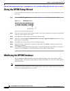
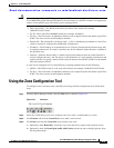
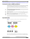
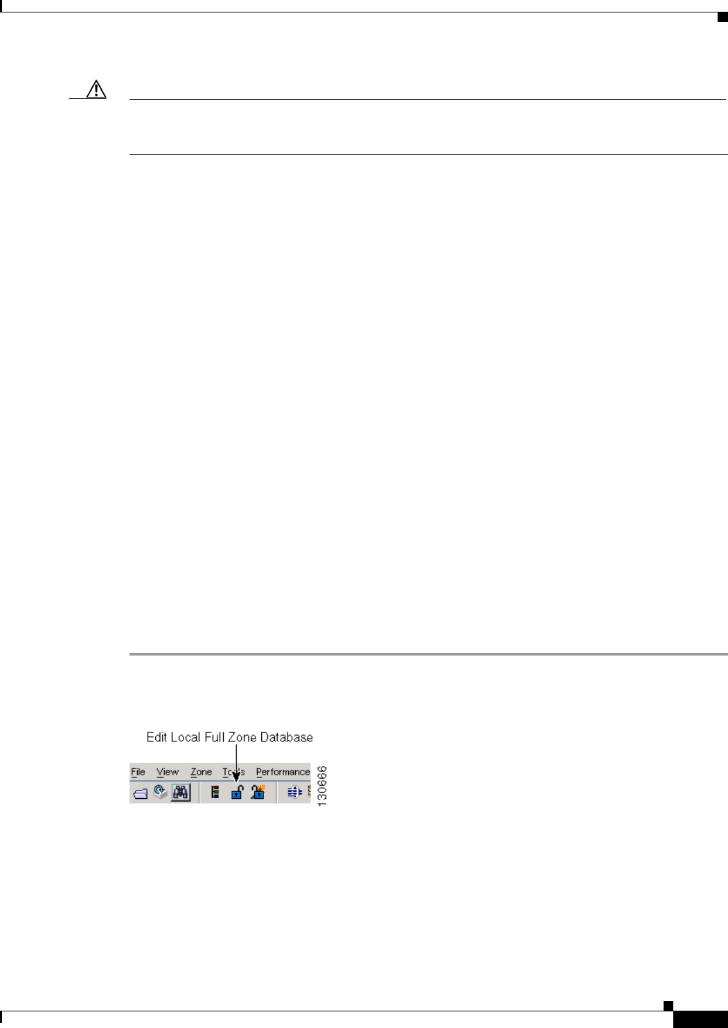
Step 1 From the Fabric Manager toolbar, click the Zone icon as shown in Figure 15-1.
Figure 15-1 Zone Icon
Step 2 Select the VSAN where you want to configure zone sets, zones, or add members to a zone.
Step 3 Click Zoneset and click the Create Row icon to make a new zone set.
Step 4 Click Zones and click the Create Row icon to make a new zone.
a. Optionally, check Read Only check box if you want the zone to permit reads and deny writes.
b. Optionally, check the Permit QoS traffic with Priority check box and set the QoS priority from
the drop-down menu.