


Send documentation comments to mdsfeedback-doc@cisco.com.
19-3
Cisco MDS 9000 Family Fabric Manager Configuration Guide
OL-6965-03, Cisco MDS SAN-OS Release 2.x
Chapter 19 FCIP Configuration
FCIP Configuration
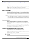
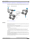
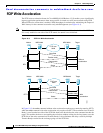
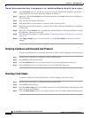
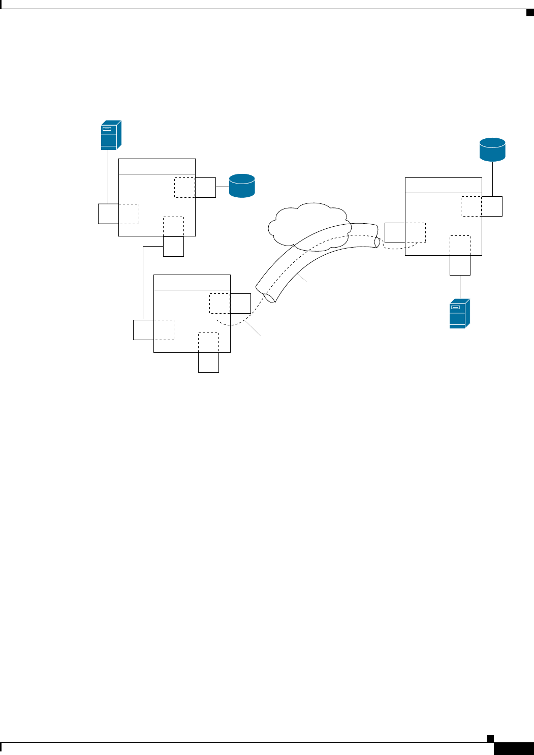
A virtual ISL is established over a FCIP link and transports Fibre Channel traffic. Each associated virtual
ISL looks like a Fibre Channel ISL with either an E port or a TE port at each end (see Figure 19-2).
Figure 19-2 FCIP Links and Virtual ISLs
See the “E Port” section on page 18-2.
FCIP Links
FCIP links consist of one or more TCP connections between two FCIP link endpoints. Each link carries
encapsulated Fibre Channel frames.
When the FCIP link comes up, the VE ports at both ends of the FCIP link create a virtual Fibre Channel
(E)ISL and initiate the E port protocol to bring up the (E)ISL.
By default, the FCIP feature on any Cisco MDS 9000 Family switch creates two TCP connections for
each FCIP link.
• One connection is used for data frames.
• The other connection is used only for Fibre Channel control frames, that is, switch-to-switch
protocol frames (all Class F). This arrangement provides low latency for all control frames.
To enable FCIP on the IP services modules, an FCIP profile and FCIP interface (interface FCIP) must
be configured.
The FCIP link is established between two peers, the VE port initialization behavior is identical to a
normal E port. This behavior is independent of the link being FCIP or pure Fibre Channel and is based
on the E port discovery process (ELP, ESC).
Once the FCIP link is established, the VE port behavior is identical to E port behavior for all inter-switch
communication (including domain management, zones, and VSANs). At the Fibre Channel layer, VE
port, and E port operations are identical.
FC
FC
FC
F
F
E
Switch A
GE
FC
FC
VE
F
F
Switch C
FC
GE
FC
E
VE
F
Switch B
FCIP link
Virtual ISL
IP
91557