


5 Basic Instruction
5.12 MC, MCR
88
FXCPU Structured Programming Manual
[Basic & Applied Instruction]
Function and operation explanation
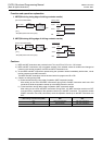
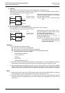
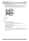
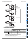
When MC instruction is executed, instructions from MC to MCR are executed. When MC instruction is not
executed, the operation with the contact OFF is executed.
In the program example below, the instructions from MC to MCR are executed as they are while the input
X000 is ON. However, while the input X000 is OFF, each drive device offers the following operation.
Timers (except retentive type timers) and devices driven by OUT instruction: Turn OFF
Retentive type timers, counters and devices driven by SET/RST instruction : Hold the current status.
Caution
1) Some restrictions to applicable devices
S1: Excluding special auxiliary relays (M)
2) Use MC instruction and MCR instruction at a same nesting level as a pair.
3) Do not attach a contact before MCR instruction. (Always make MCR instruction "TRUE".)
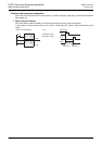
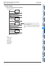
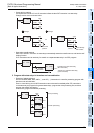
4) When not adopting the nesting structure
Use the nesting level "0" for creating a program.
MC instruction can use the same nesting level "0" as many times as needed by changing the device (Y or
M) number specified by .
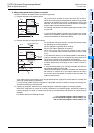
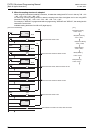
5) When adopting the nesting structure
Increase the nesting level in the way "0 → 1 → ... → 6 → 7".
→ Refer to a program example for the details.
6) The device specified by remains ON while MC instruction is executed.
If the same device number is used in another instruction, it results in the double coil operation in the same
way as OUT instruction.
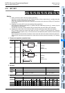
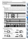
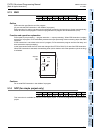
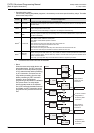
MC(X000,0,M100);
Y000:= X001;
Y001:= X002;
MCR(TRUE,0);
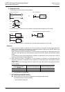
[Structured ladder/FBD]
[ ST ]
X000
X001
X002
MC
EN ENO
d
n
MCR
EN ENO
n
0 M100
Y000
Y001
0