


14 Applied Instructions (External FX I/O Device)
14.3 DSW / Digital Switch (Thumbwheel Input)
363
FXCPU Structured Programming Manual
[Basic & Applied Instruction]
11
Applied Instructions
(Data Operation)
12
Applied Instructions
(High Speed
Processing)
13
Applied Instructions
(Handy
Instruction)
14
Applied Instructions
(External FX I/O
Device)
15
Applied Instructions
(External Device
(optional device))
16
Applied Instructions
(External Device)
17
Applied Instructions
(Data Transfer 2)
18
Applied Instructions
(Floating Point)
19
Applied Instructions
(Data Operation 2)
20
Applied Instructions
(Positioning
Control)
Program examples
This is an example of explaining connection of digital switch starting from the input X010 and starting from the
digit designation output Y010.
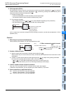
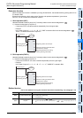
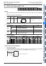
1. Program
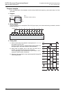
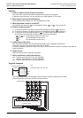
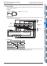
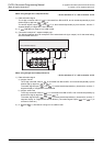
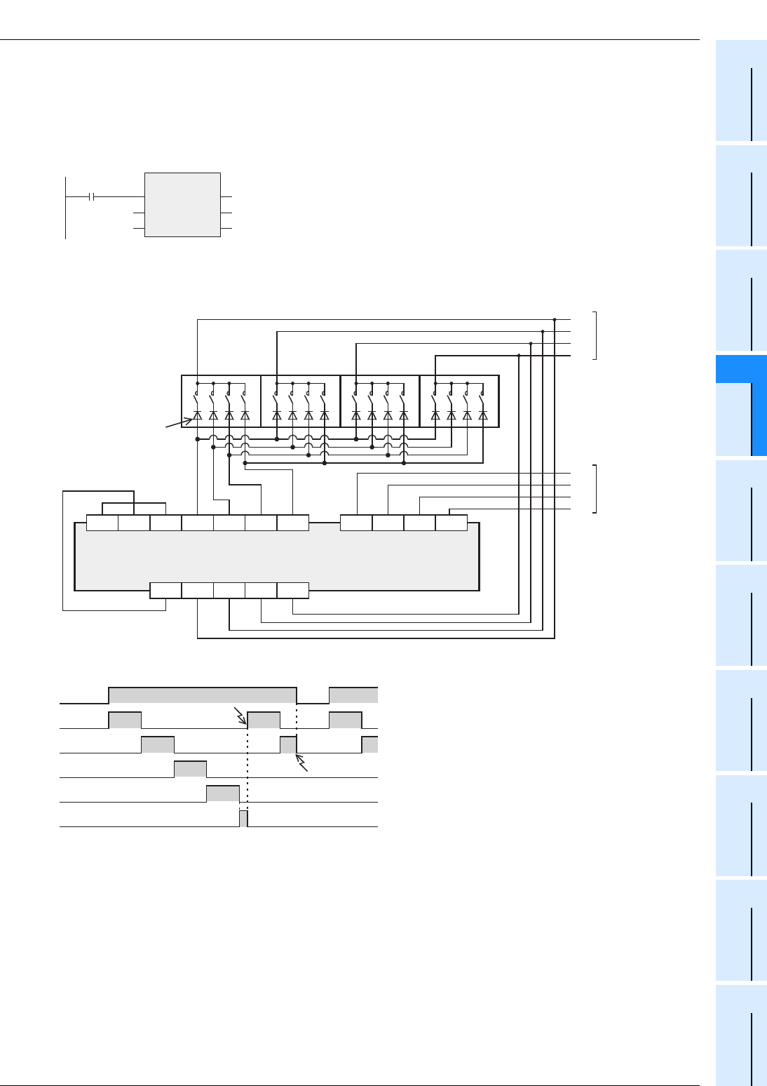
2. Wiring diagram
This wiring connection diagram is an example of basic unit of FX3U series (sync input/sync output). As for the
actual wiring, see the manual of the PLC.
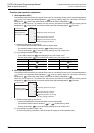
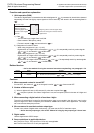
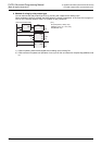
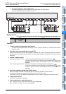
3. Timing chart
Y010 to Y013 are turned ON sequentially in every 100 ms while X000 is being turned ON, and when
operation of one cycle is over, the execution complete flag M8029 is set up.
X000
DSW
EN
s
n
ENO
d1
d2
X10
Y10
D0K1
DSW(X000, X10, K1, Y10, D0);
[Structured ladder/FBD] [ST]
10
3
10
2
10
1
10
0
Digital switch
of BCD
10
3
10
2
10
1
10
0
To second set
Diode of 0.1 A,
50 V is needed.
Digital switch
of BCD
4
3
2
1
To second set
8421
S/S X010 X011 X012 X013 X015X014 X016 X017
COM3
Y010 Y011 Y012 Y013
First set input
PLC
1248
10
3
10
2
10
1
10
0
Second set input
24V 0V
X000
Y010
Y011
Y012
Y013
M8029 Complete flag
Repeated
operation
0.1 sec 0.1 sec 0.1 sec
0.1 sec
0.1 sec
0.1 sec
Interrupt