


31 Applied Instructions (Data Transfer 3)
31.1 RBFM / Divided BFM Read
733
FXCPU Structured Programming Manual
[Basic & Applied Instruction]
31
Applied Instructions
(Data Transfer 3)
32
Applied Instructions
(High Speed
Processing 2)
33
Applied Instructions
(Extension File
Register Control)
34
Applied Instructions
(FX
3U
-CF-ADP)
35
Interrupt Function
and Pulse Catch
Function
A
Relationships
between devices
and addresses
B
Applied
Instruction List
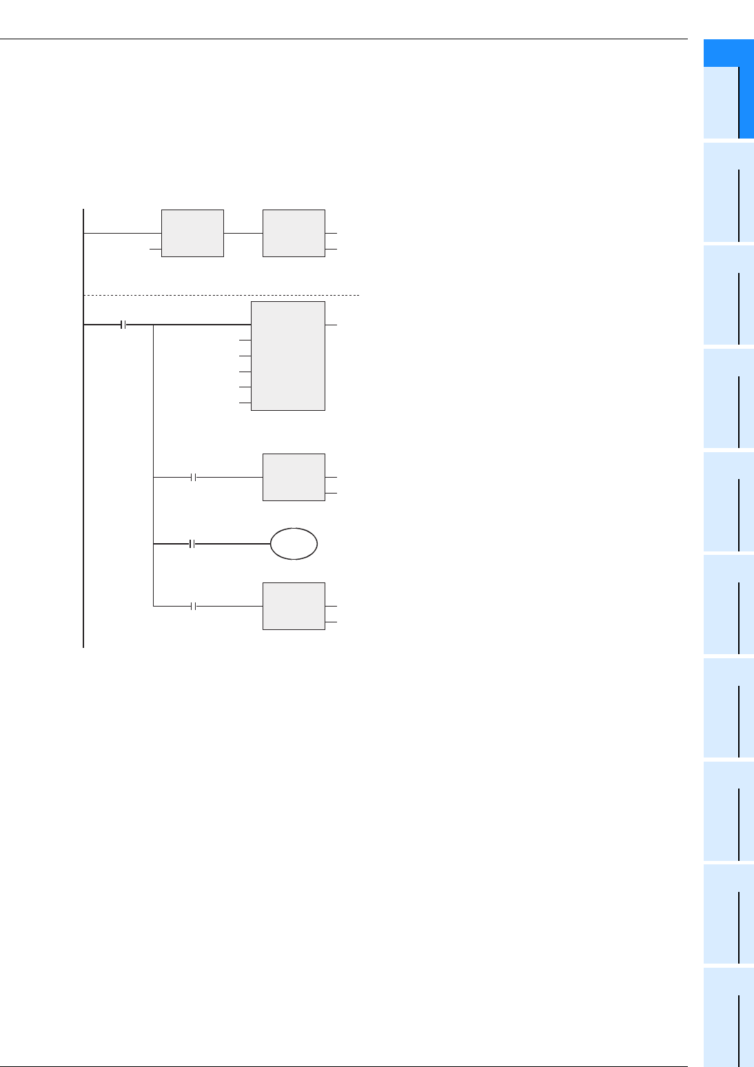
Program example
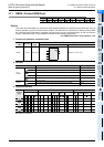
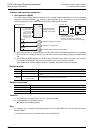
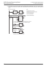
In the program example shown below, data is read from and written to the buffer memories (BFM) in the unit
No. 2 as follows:
1) When X000 is set to ON, data stored in D100 to D179 (80 points) are written to the buffer memories
(BFM) #1001 to #1080 in the special function block and unit whose unit number is No. 2 by 16 points in
each operation cycle.
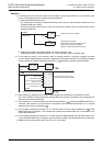
[Structured ladder/FBD]
The BFM write start
flag is set to ON.
BFM write
start
BFM write start
Instruction
execution complete
Instruction execution
abnormally complete
D100 to D179 (80 points) are written to the buffer memories
#1001 to #1080 in the unit No. 2 (in 5 operation cycles).
The BFM write start flag is set to OFF.
Execution of the WBFM
instruction is waited.
Y000
Instruction
non-execution
LDP
EN
s
ENO
X000
SET
EN ENO
d
M0
M0
WBFM
EN ENO
m1
m2
s
n1
n2
K2
K1001
D100
K80
K16
RST
EN ENO
d
M0
M8029
M8328
RST
EN ENO
d
M0
M8329
The BFM write start flag is set to OFF.
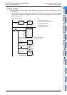
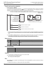
[ST]
SET(LDP(TRUE,X000),M0);
WBFM(M0,K2,K1001,D100,K80,K16);
RST(M0 AND M8029,M0);
Y000:=M0 AND M8328;
RST(M0 AND M8329,M0);