


15 Applied Instructions (External Device (optional device))
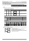
15.7 VRSC / Volume Scale
410
FXCPU Structured Programming Manual
[Basic & Applied Instruction]
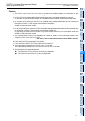
Cautions
1) The FX1NC, FX2NC and FX3GC PLCs are not provided with variable resistors for reading out by this
instruction, and hence do not function even if programmed.
2) In FX
3S PLCs, the variable analog potentiometer board can be connected to the option connector.
In this case, the communication function is not available when the VRRD or VRSC instruction is used.
3) In 14-point and 24-point type FX
3G PLCs, the variable analog potentiometer board can be connected to
the option connector 1, and occupies communication channel ch1.
In this case, the communication function using communication channel ch1 is not available when the
VRRD or VRSC instruction is used.
4) In 40-point and 60-point type FX
3G PLCs, the variable analog potentiometer board can be connected only
to the option connector 2, and occupies communication channel ch2.
In this case, the communication function using communication channel ch2 is not available when the
VRRD or VRSC instruction is used.
5) The communication function is not available for ch1 when the VRRD or VRSC instruction is used in the
program in FX
3S, FX3U and FX3UC PLCs.
→ For details, refer to the Communication Control Edition manual.
6) FX
3S and FX3G PLCs support the FX3G-8AV-BD.
7) FX
3U and FX3UC-32MT-LT(-2) PLCs support the FX3U-8AV-BD.
8) The instruction is provided in the FX
3G PLC Ver. 1.10 or later.
The instruction is provided in the FX
3U and FX3UC PLCs Ver. 2.70 or later.
9) Some restrictions to applicable devices.
S1: The FX
3S, FX3G, FX3U and FX3UC PLCs only are applicable.
S2: The FX
3G, FX3U and FX3UC PLCs only are applicable.
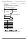
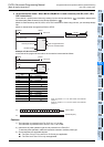
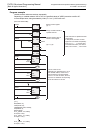
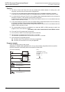
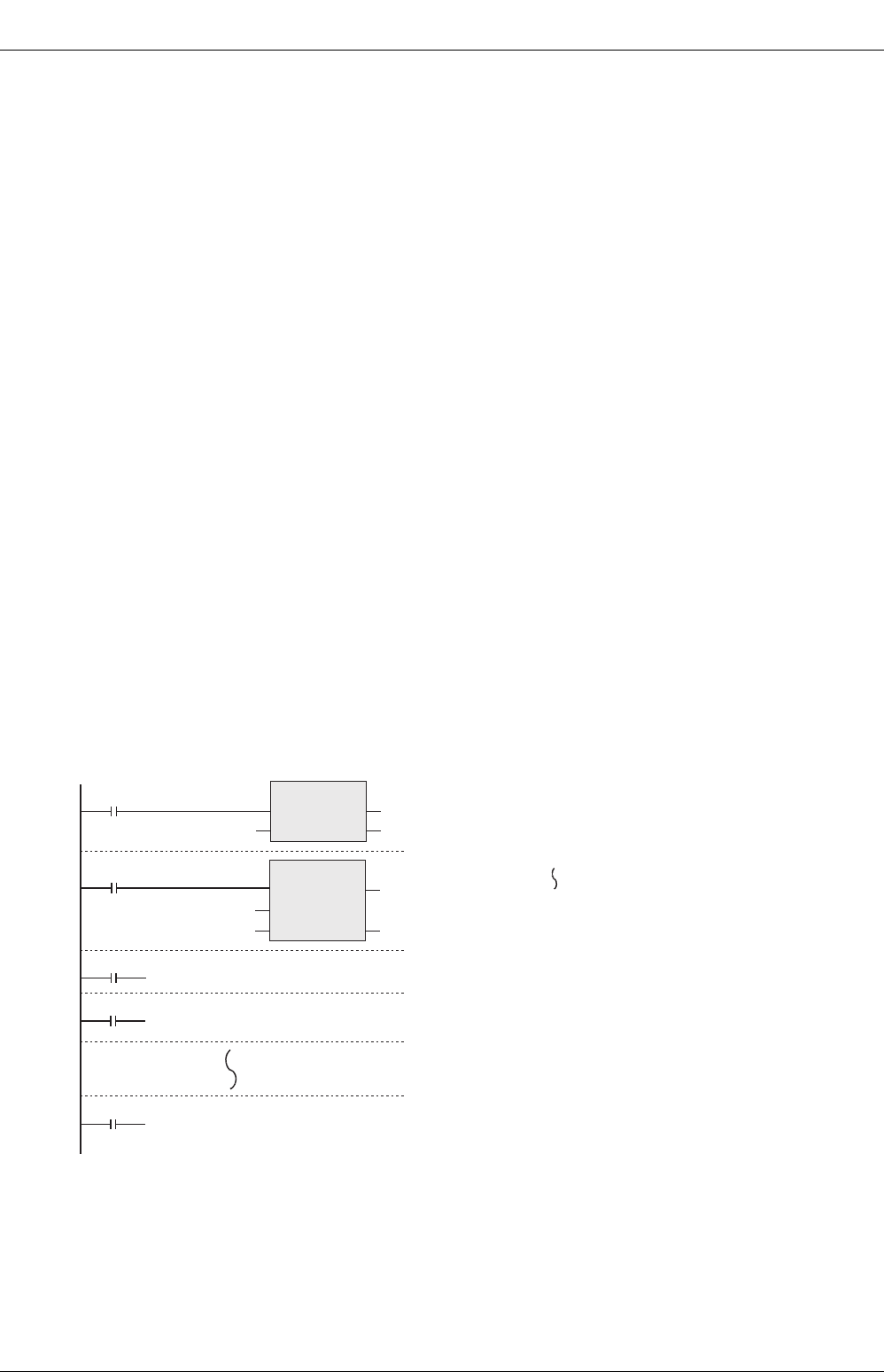
Program example
This is an example of use as rotary switch.
Depending on variable resistor graduations 0 to 10, any one of auxiliary relays M0 to M10 is turned ON.
By DECO instruction, the auxiliary relays are occupied from M0 to M15.
[Structured ladder/FBD]
DECO
EN
s
n
ENO
D1
K4
d
M0
X000
VRSC
EN ENO
d
D1
M0
X001
ON at graduation 0
s
K1
M1
M10
ON at graduation 1
ON at graduation 10
[ ST ]
VRSC(X000, K1, D1);
DECO(X001, D1, K4, M0);
OUT(M0, ···);
OUT(M1, ···);
OUT(M10, ···);