


35 Interrupt Function and Pulse Catch Function
792
FXCPU Structured Programming Manual
[Basic & Applied Instruction]
35.1 Outline
35. Interrupt Function and Pulse Catch Function
This chapter explains the built-in interrupt function and pulse catch function in FX PLCs.
The input, special devices and timers in the explanations relate to the FX
3U and FX3UC PLCs. Note that these
differ from one model of PLC to another.
→ FX Structured Programming Manual [Device & Common]
35.1 Outline
This section explains the function to immediately execute an interrupt program (interrupt routine) without
being affected by the operation cycle of the sequence program (main) while using an interrupt function as a
trigger.
The delay by operation cycle and machine operation affected by uneven time intervals in normal sequence
program process can be improved.
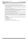
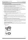
1. Input interrupt function (interrupt of external signal input (X))
By the input signal from an input (X000 to X005), the normal sequence program is paused, and an interrupt
routine program is executed with priority.
The input interrupt execution timing can be specified on the rising edge or falling edge of the signal by the
pointer number.
→ For details, refer to Section 35.3.
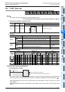
2. Input interrupt delay function (interrupt of external signal input (X))
By the input signal from an input (X000 to X005), the normal sequence program is paused, and an interrupt
routine program is executed with priority after the delay time (set in units of 1 ms).
The input interrupt execution timing can be specified on the rising edge or falling edge of the signal by the
pointer number.
→ For details, refer to Section 35.4.
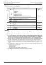
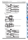
3. Timer interrupt function (timer interrupt activated in a constant cycle)
The normal sequence program is paused in a constant cycle of 10 to 99 ms, and an interrupt routine program
is executed with priority.
→ For details, refer to Section 35.5.
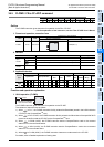
4. High speed counter interrupt function (interrupt function given at counting up)
When the current value of a high speed counter reaches a specified value, the normal sequence program is
paused and an interrupt routine program is executed with priority.
→ For details, refer to Section 35.6.
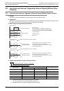
5. Pulse catch function
When the input signal from an input (X000 to X007) turns ON from OFF, a special auxiliary relay ;M8170 to
M8177 is set in the interrupt processing. By a relay M8170 to M8177 in a normal sequence program, a signal
that remains ON longer than the receivable range with regular input processing can be easily received.
When processing such a signal that turns ON and OFF several times in one operation cycle, however, use
the input interrupt function.
→ For details, refer to Section 35.7.
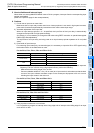
6. Pulse width/Pulse period measurement function
When the input signal from an input (X000, X001, X003 or X004) turns from OFF to ON, the value of the 1/6
μs ring counter at the input signal rising edge is stored in special data registers.
When the input signal turns OFF from ON, the value of the 1/6 μs ring counter at the input signal falling edge
is stored in special data registers. At the same time, the difference in the counter value between the rising
edge and the falling edge is divided by "60", and the pulse width in units of 10 μs is stored in special data
registers.
In the pulse period measurement mode, when the input signal turns from OFF to ON, the difference between
the previous rising of the input signal and the current rising of the input signal is divided by "60", and then the
pulse period in units of 10 μs is stored in special data registers.
→ For details, refer to Section 35.8.