


1 Outline
1.3 Cautions on Creation of Fundamental Programs
25
FXCPU Structured Programming Manual
[Basic & Applied Instruction]
1
Outline
2
Instruction List
3
Configuration of
Instruction
4
How to Read
Explanation of
Instructions
5
Basic Instruction
6
Step Ladder
Instructions
7
Applied Instructions
(Program Flow)
8
Applied Instructions
(Move and
Compare)
9
Applied Instructions
(Arithmetic and
Logical Operation)
10
Applied Instructions
(Rotation and
Shift Operation)
1.3.5 Handling of operation error flag
When there is an error in the sequence instruction configuration, target device or target device number range
and an error occurs while operation is executed, the following flag turns ON and the error information is store.
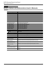
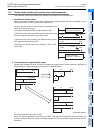
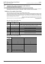
1. Operation error
*1. When the error occurrence step is up to the 32767th step in FX3U and FX3UC PLCs, the error
occurrence step can be checked in D8069 (16 bits).
• When an operation error has occurred, M8067 is set, D8067 stores the operation error code number, and
the device storing error occurrence step (see the table above) stores the error occurrence step number.
• If another error occurs in another step, the stored data is updated in turn to the error code and step number
of the new error. (These devices are set to OFF when errors are cleared.)
• When the PLC mode switches from STOP to RUN, these devices are cleared instantaneously, and then
set to ON again if errors have not been cleared.
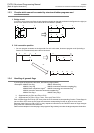
2. Operation error latch
*2. When the error occurrence step is up to the 32767th step in FX3U and FX3UC PLCs, the error
occurrence step can be checked in D8068 (16 bits).
• When an operation error has occurred, M8068 is set, and the device storing error occurrence step (see the
table above) stores the error occurrence step number.
• Even if another error has occurred in another step, the stored data is not updated, and remains held until
these devices are forcibly reset or until the power turns OFF.
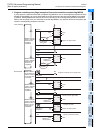
1.3.6 Handling of function extension flag
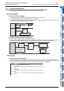
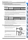
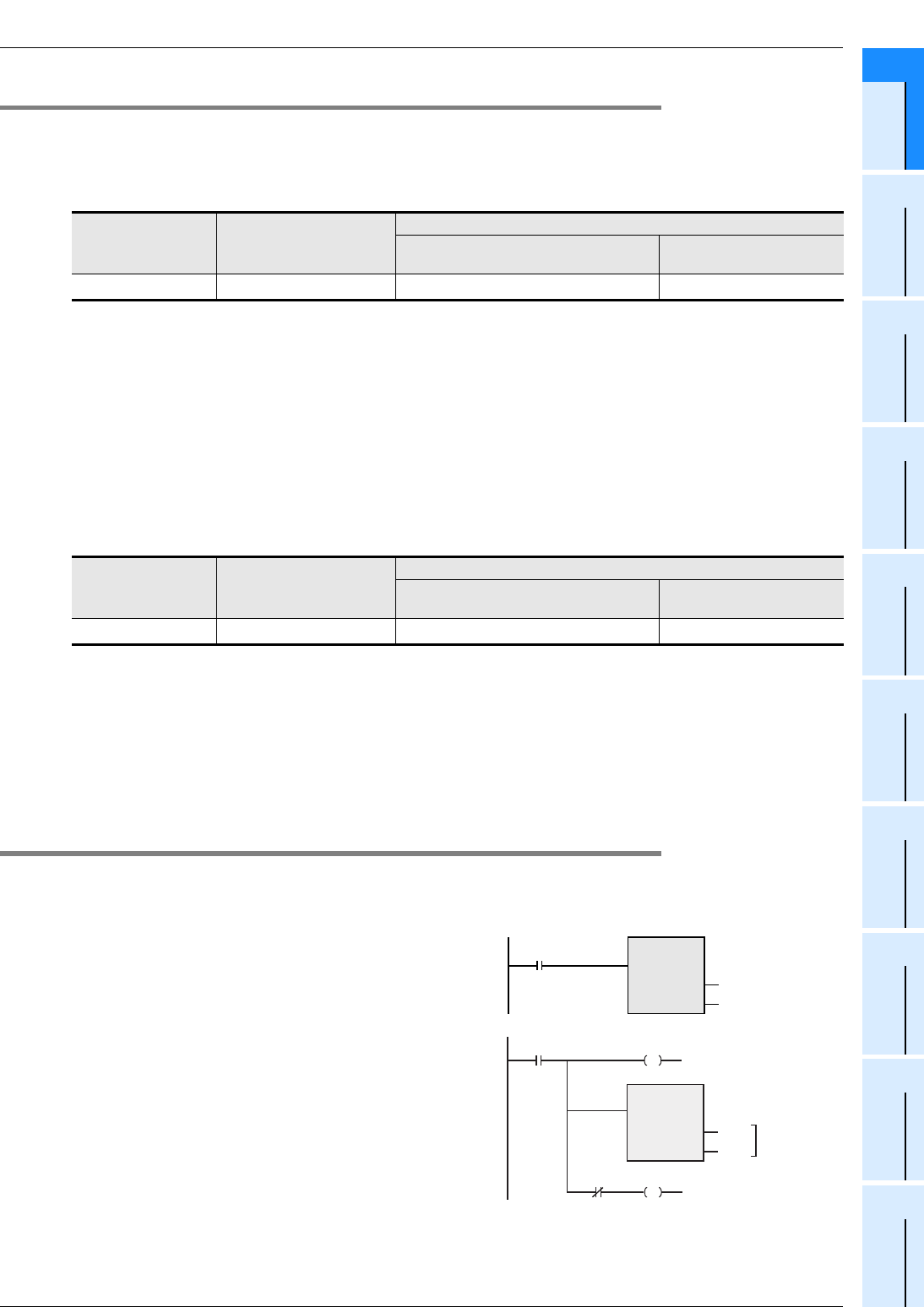
In some sequence instructions, the function can be extended by combining a specific special auxiliary relay
determined for each sequence instruction. An example is explained below.
• When X000 turns ON, this instruction exchanges the
contents of D10 and D11 with each other.
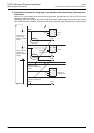
• If M8160 has been driven before the XCH function and
the source and destination of the XCH instruction are
specified to the same device, high-order 8 bits and low-
order 8 bits are exchanged with each other inside the
device.
• For returning this XCH to the normal XCH function, it is
necessary to set M8160 to OFF.
When using an instruction requiring the function extension flag in an interrupt program, program DI function
(for disabling interrupt) before driving the function extension flag, and program EI function (for enabling
interrupt) after turning OFF the function extension flag.
Error flag Device storing error code
Device storing error occurrence step
FX0S/FX0/FX0N/FX1S/FX1N/FX1NC/
FXU/FX2C/FX2N/FX2NC/FX3S/FX3G/FX3GC
FX3U/FX3UC
M8067 D8067
D8069
*1
D8315, D8314
Error flag Device storing error code
Device storing error occurrence step
FX0S/FX0/FX0N/FX1S/FX1N/FX1NC/
FXU/FX2C/FX2N/FX2NC/FX3S/FX3G/FX3GC
FX3U/FX3UC
M8068 -
D8068
*2
D8313, D8312
X000
XCHP
EN ENO
d1
D10
d2
D11
X000
Same
number
Function extension flag
for the XCH instruction
XCHP
EN ENO
d1
D10
d2
D10
M8160
M8160M8000