


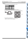
8 Applied Instructions (Move and Compare)
8.5 CML / Complement
147
FXCPU Structured Programming Manual
[Basic & Applied Instruction]
1
Outline
2
Instruction List
3
Configuration of
Instruction
4
How to Read
Explanation of
Instructions
5
Basic Instruction
6
Step Ladder
Instructions
7
Applied Instructions
(Program Flow)
8
Applied Instructions
(Move and
Compare)
9
Applied Instructions
(Arithmetic and
Logical Operation)
10
Applied Instructions
(Rotation and
Shift Operation)
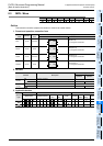
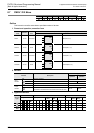
Function and operation explanation
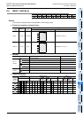
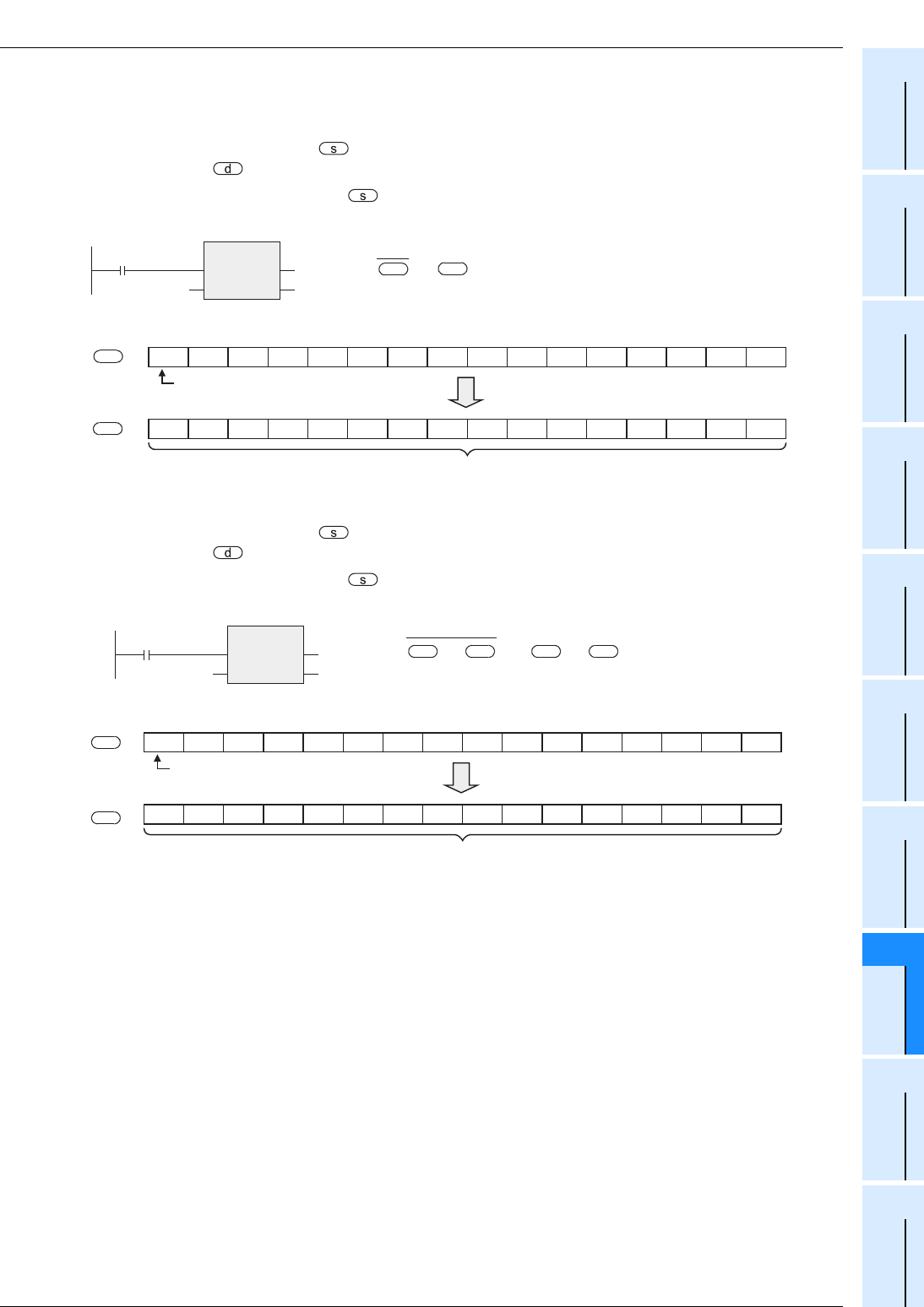
1. 16-bit operation(CML, CMLP)
Each bit of a device specified by is inverted (from 0 to 1 or from 1 to 0), and then transferred to the
device specified by .
• When a constant (K) is specified as , it is automatically converted into binary.
• This operation is useful when a logically inverted output is required as an output from a PLC.
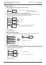
2. 32-bit operation(DCML, DCMLP)
Each bit of a device specified by is inverted (from 0 to 1 or from 1 to 0), and then transferred to the
device specified by .
• When a constant (K) is specified as , it is automatically converted into binary.
• This operation is useful when a logically inverted output is required as an output from a PLC.
Cautions
1) Some restrictions to applicable devices
S1:The FX
3G, FX3GC, FX3U and FX3UC PLCs only are applicable.
S2:The FX3U and FX3UC PLCs only are applicable.
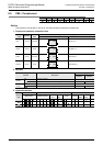
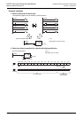
CML
EN
s
ENO
d
Command input
Data to be
inverted
Data having been inverted
sign bit
(0=Positive number 1=Negative number)
0101110001010101
0 1 0 1 0 1 0 1 1 1 0 0 0 1 0 1
Inverted data is transferred.
Command contact=ON
s
b15 b14 b13 b12 b11 b11 b9 b8 b7 b6 n5 b4 b3 b2 b1 b0
d
→
d
s
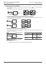
010111001010101
0 1 0 1 0 1 0 1 1 0 0 0 1 0 1
b31 b30 b29 b28 b27 b26 b25 to b7 b6 n5 b4 b3 b2 b1 b0
s
d
DCML
EN
s
ENO
d
Command input
→+1,
ds s
+1,
d
sign bit
(0=Positive number 1=Negative number)
Inverted data is transferred.
Command contact=ON
Data to be
inverted
Data having been inverted