


14 Applied Instructions (External FX I/O Device)
14.6 ARWS / Arrow Switch
375
FXCPU Structured Programming Manual
[Basic & Applied Instruction]
11
Applied Instructions
(Data Operation)
12
Applied Instructions
(High Speed
Processing)
13
Applied Instructions
(Handy
Instruction)
14
Applied Instructions
(External FX I/O
Device)
15
Applied Instructions
(External Device
(optional device))
16
Applied Instructions
(External Device)
17
Applied Instructions
(Data Transfer 2)
18
Applied Instructions
(Floating Point)
19
Applied Instructions
(Data Operation 2)
20
Applied Instructions
(Positioning
Control)
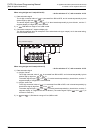
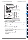
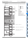
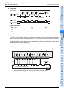
• When writing in
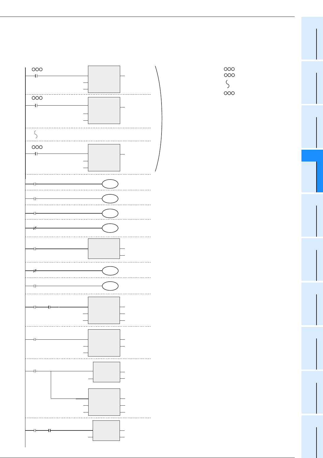
Press the X003 by setting the numeric value while observing the 7-segment display by the arrow switch.
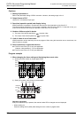
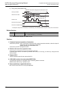
Program
M8000
X000
M 0
Decrement
X001
M 1
Increment
X002
M 2
Carry down
RUN monitor
M 3
Carry over
X004
Read/Write
M100
Y014
Read display
M100
Y015
Write display
Y014 X003
Read
out
Setting
Y014
Read out
Y015
Write in
MOVP
EN
s
ENO
d
D300Z
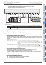
[Structured ladder/FBD]
OUT_T
EN
TCoil
TValue
ENO
TC0
D300
OUT_T
EN
TCoil
TValue
ENO
TC1
D301
ALTP
EN ENO
d
M100
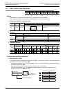
DSW
EN
s
n
ENO
d1
d2
X010
Y010
ZK1
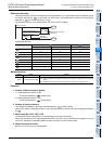
ARWS
EN
s
n
ENO
d1
d2
M0
D511
K1
SEGL
EN
s
n
ENO
d
T0Z
Y000
K1
X
X
X
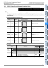
Digital switch → Z, 4 digits, 1 set
4 digits, 1 set TOZ → 7-segment negative logic
(M0 to M3) → (D511) → (Y000 to Y007)
→ 7-segment 1 digit, 1 set
Practical
timer circuit
D511
Y000
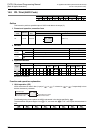
OUT_T
EN
TCoil
TValue
ENO
TC99
D399
Y015 X003
Write
in
Setting
MOVP
EN
s
ENO
d
D511
D300Z
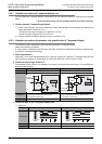
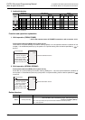
OUT_T(X , TC0, D300);
[ ST ]
OUT_T(X , TC1, D301);
OUT_T(X , TC99, D399);
M0:= X000;
M1:= X001;
M2:= X002;
M3:= NOT M8000;
ALTP(X004, M100);
Y014:= NOT M100;
Y015:= M100;
DSW(Y014 AND X003, X010,
K1, Y010, Z);
SEGL(Y014, T0Z, K1, Y000);
MOVP(Y015, D300Z, D511);
ARWS(Y015, M0, K1, D511, Y000);
MOVP(Y015 AND X003, D511, D300Z);