


13 Applied Instructions (Handy Instruction)
13.9 ROTC / Rotary Table Control
348
FXCPU Structured Programming Manual
[Basic & Applied Instruction]
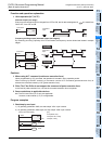
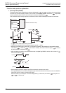
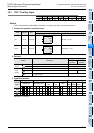
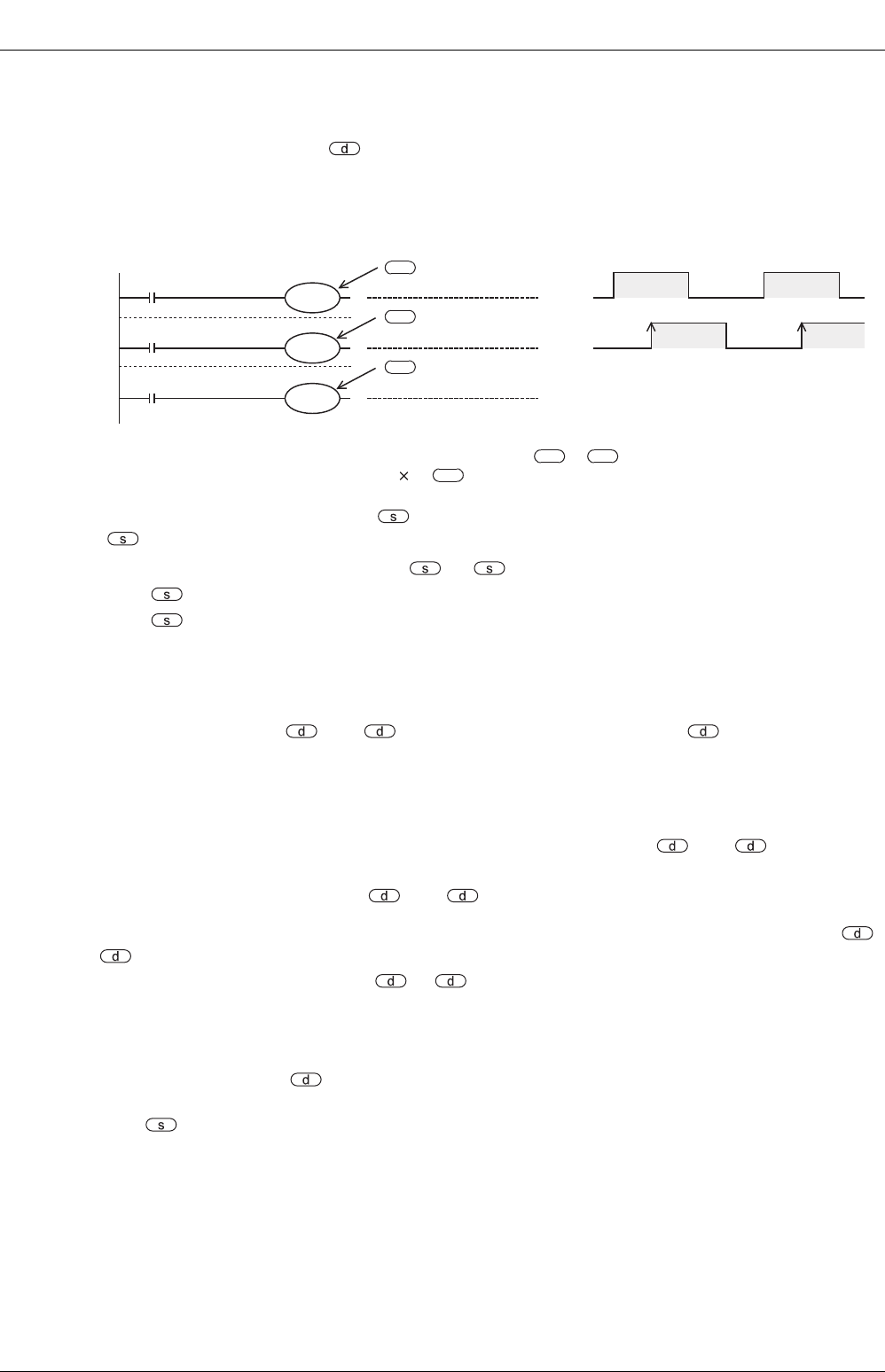
Operation condition
The condition necessary for using this command is as shown in the example below.
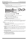
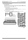
1) Rotation detection signal: X→
a) Please install two-phase switch (X000, X001) for detecting normal rotation/reverse rotation of table,
and switch X002 for operating when article number 0 comes to window number 0.
b) Create sequence program as shown in the example below.
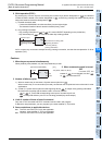
2) Designation of register for counting:
is a counter for counting article of which number is coming to window number 0.
3) Designation register of calling condition: +1, +2
a) In +1, you can set the window number desired to be called.
b) In +2, you can set the article number desired to be called.
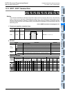
4) Division number m1 and low speed period m2
To designate division number m1 of table and low speed operation section m2.
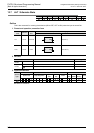
When the above condition is designated, the output of normal/reverse rotation, high speed/low speed/stop will
be obtained in the output of +3 to +7 designated in the beginning device of the command.
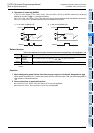
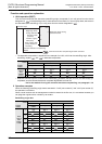
Cautions
1. Operation by ON/OFF of command input
• When this command is driven by turning ON the command input, results of +3 to +7 will be
obtained automatically.
• By turning OFF the command input, +3 to +7 are turned OFF.
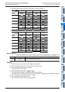
2. Operation of plural times in one division section of article of rotation detection signal (
to +2)
For example, rotation detection signal ( to +2) operates 10 times in one division section of article,
setting of division number, setting of calling window number, and setting of article number should be all
multiplied by 10.
As a result, the set value of low speed section can be set in an intermediate value of division number.
3. 0 point detection signal
When the command input is ON and 0 point detection signal (M2) is turned ON, the content of register for
counting is cleared to 0. You must start operation by executing this clearing operation beforehand.
4. Some restrictions to applicable devices.
S1: The FX3U and FX3UC PLCs only are applicable.
However, index modifier (V, Z) is not applicable.
S2: The FX
3U and FX3UC PLCs only are applicable.
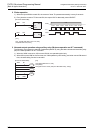
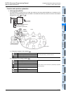
X000
M0
X001
M1
X002
M2
0 point detection switch
Two-phase switch
Phase B
Phase A
Up-count signal in normal rotation
+1
+2
d
d
d
By X000 to X002, you can exchange with internal contacts of to +2.
Beginning device number for designating or is arbitrary.
d
d d