


7 Applied Instructions (Program Flow)
7.2 CALL / Call Subroutine
114
FXCPU Structured Programming Manual
[Basic & Applied Instruction]
Cautions on subroutines and interrupt routines
This section explains cautions on creating programs in subroutines and interrupt routines.
The explanation below is given for subroutines, but the situation also applies to interrupt routines.
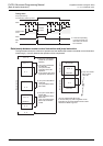
1. When using timers in subroutines (or interrupt routines)
Use retentive type timers T192 to T199 in subroutines.
These timers execute counting when the coil instruction or END instruction is executed.
After a timer reaches the set value, the output contact is activated when the coil instruction or END instruction
is executed.
Because general timers execute counting only when the coil instruction is executed, they do not execute
counting if they are used in subroutines in which the coil instruction is executed only under some conditions.
2. When using retentive type 1 ms timers in subroutines (or interrupt routines)
If a retentive type 1 ms timer is used in a subroutine, note that the output contact is activated when the first
coil instruction (or subroutine) is executed after the timer reaches its set value.
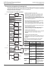
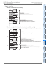
3. Countermeasures against latches of devices used in subroutines (or interrupt routines)
Devices which were set to ON in a subroutine are latched in the ON status even after the subroutine is
finished. (Refer to the program described later.)
When RST instruction for a timer or counter is executed, the reset status of the timer or counter is latched
also.
For turning OFF such a device latched in the ON status or for canceling such a timer or counter latched in the
reset status, reset such a device in the main program after the routine is finished, or program a sequence for
resetting such a device or for deactivating RST instruction in the routine. (Refer to the program described
later.)
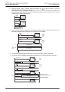
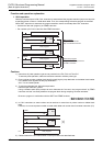
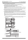
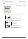
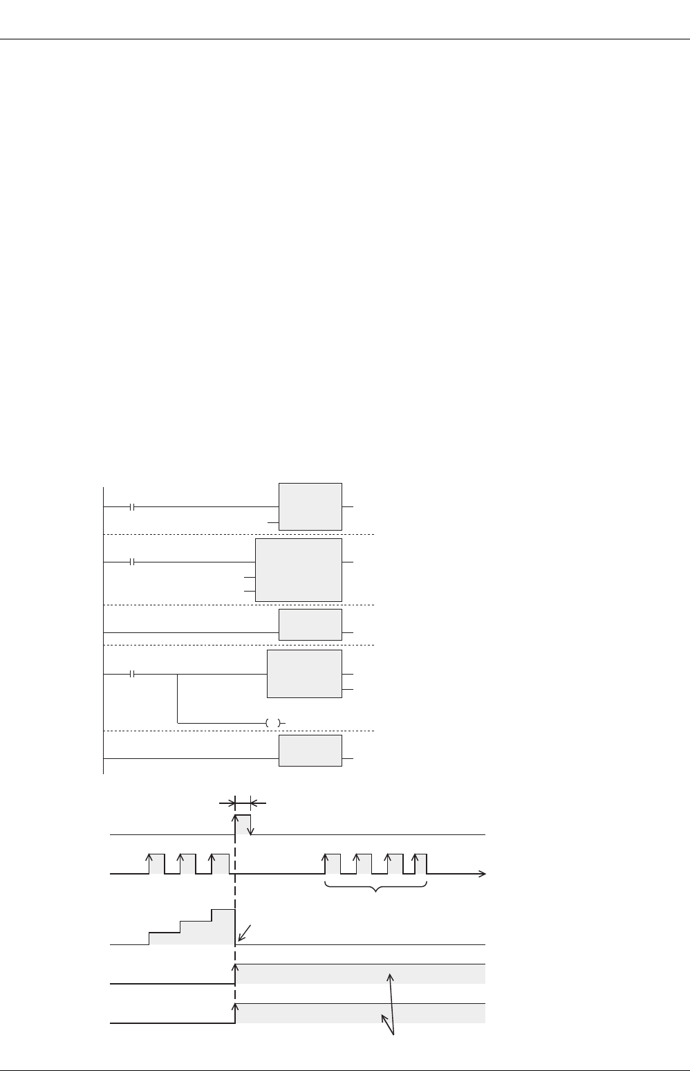
1) Example in which outputs are latched
In the following program example, the counter C0 is provided to count X001. When X000 is input, the
subroutine P0 is executed only in one scan, and then the counter is reset and Y007 is output.
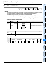
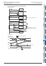
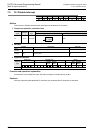
• Program examples
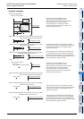
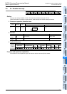
• Timing chart
X000
X000
X001
P0:
CALLP
EN ENO
p
SRET
EN ENO
FEND
EN ENO
OUT_C
EN ENO
CCoil
CValue
RST
EN ENO
d
Y007
P0
CC0
K10
CN0
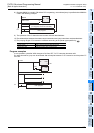
Execution of subroutine
P0 triggered by X000
X001
Current value
of C0
1
2
3
Counter is
reset.
Because the reset instruction for C0 is valid,
the current value of C0 remains unchanged
even if pulses are input.
Remains reset
Y007 is being output.
Outputs are held.
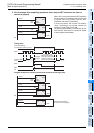
RST
C0
Y007
Subroutine is executed.