


30 Applied Instructions (External Device Communication)
30.7 ADPRW / MODBUS Read/Write
727
FXCPU Structured Programming Manual
[Basic & Applied Instruction]
21
Applied Instructions
(Real Time
Clock Control)
22
Applied Instructions
(External Device)
23
Applied Instructions
(Extension
Function)
24
Applied Instructions
(Others)
25
Applied Instructions
(Block Data
Operation)
26
Applied Instructions
(Character
String Control)
27
Applied Instructions
(Data Operation 3)
28
Applied Instructions
(Data Comparison)
29
Applied Instructions
(Data Table
Operation)
30
Applied Instructions
(External Device
Communication)
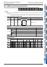
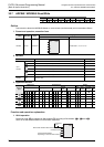
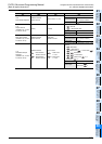
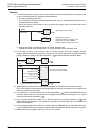
10H
Write Multiple Registers
MODBUS Address:
0000H to FFFFH
Device Count: 1 to 123
PLC Source Device (head address)
Applicable Devices
D, R, K, H
(D, R can be indexed.)
Block Length
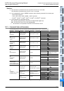
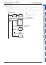
11H
Report Slave ID
(Available only in FX3U
and FX3UC PLCs)
0 (fixed) 0 (fixed)
PLC Destination Device (head address)
• : Slave ID
• +1: RUN/STOP State
Applicable Devices D, R
Block Length 2 Point
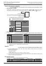
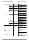
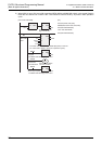
16H
Mask Write Register
(Available only in FX3U
and FX3UC PLCs)
MODBUS Address:
0000H to FFFFH
AND Mask:
0000H to FFFFH
OR Mask: 0000H to FFFFH
Applicable Devices
D, R, K, H
(D, R can be indexed.)
Block Length 1 Point
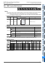
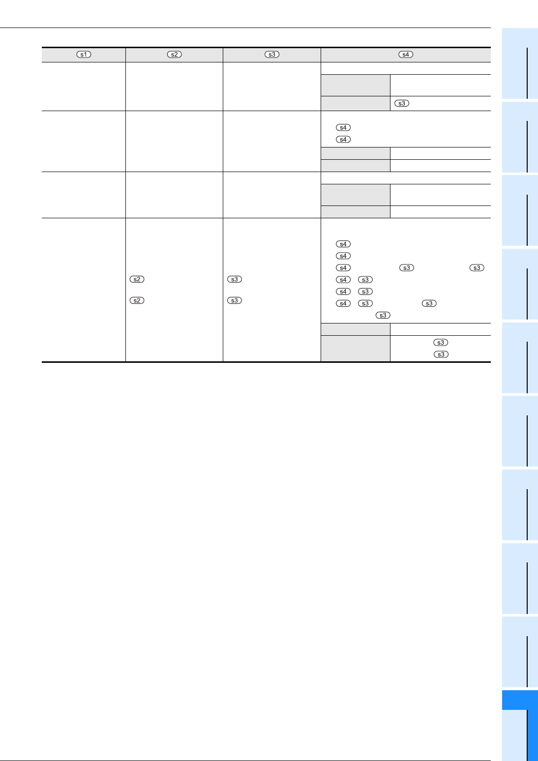
17H
Read/Write Multiple
Registers
(Available only in FX3U
and FX3UC PLCs)
MODBUS Address:
: Write Address
0000H to FFFFH
+1: Read Address
0000H to FFFFH
Device Count:
: Write Count
1 to 121
+1: Read Count
1 to 125
PLC Source Device / Destination Device (head
address)
• : Write Data 1
• +1: Write Data 2
• +(Write Count )-1: Write Data ( )
• + : Read Data 1
• + +1: Read Data 2
• + +(Read Count +1)-1:
Read Data ( +1)
Applicable Devices D, R
Block Length
Write Count +
Read Count +1