


15 Applied Instructions (External Device (optional device))
15.1 RS / Serial Communication
391
FXCPU Structured Programming Manual
[Basic & Applied Instruction]
11
Applied Instructions
(Data Operation)
12
Applied Instructions
(High Speed
Processing)
13
Applied Instructions
(Handy
Instruction)
14
Applied Instructions
(External FX I/O
Device)
15
Applied Instructions
(External Device
(optional device))
16
Applied Instructions
(External Device)
17
Applied Instructions
(Data Transfer 2)
18
Applied Instructions
(Floating Point)
19
Applied Instructions
(Data Operation 2)
20
Applied Instructions
(Positioning
Control)
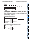
Function and operation explanation
1. 16-bit operation (RS)
This instruction sends and receives data in no-protocol communication by way of serial ports in accordance
with RS-232C or RS-485 provided in the main unit.
→ For detailed explanation, refer to the Data Communication Edition manual.
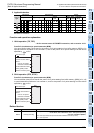
Related devices
→ For detailed explanation, refer to the Data Communication Edition manual.
*1. Not supported by the FX
0N PLC.
*2. The FX
U, FX2C PLCs are applicable at Ver.3.30 or later.
*3. Not supported by the FX
0N, FX1S, FX1N, FX1NC, FXU, FX2C, FX2N and FX2NC PLCs.
System configuration
To use this instruction, it is necessary to attach one of the products shown in the table below to the main unit.
→ For the system configuration, refer to the respective PLC Hardware Edition manual.
→ For detailed explanation, refer to the Data Communication Edition manual.
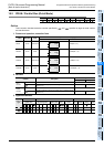
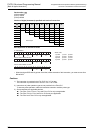
Differences between RS instruction and RS2 instruction
RS2 instruction is not provided in the FX0N, FX1S, FX1N, FX1NC, FXU, FX2C, FX2N and FX2NC PLCs.
Device Name Device Name
M8063 Serial communication error 1 D8120 Communication format setting
M8121 Sending wait flag D8122 Remaining number of data to be sent
M8122 Sending request D8123 Monitor for number of received data
M8123 Receiving complete flag D8124 Header
M8124
*1
Carrier detection flag D8125 Terminator
M8129
*2
Time-out check flag
D8129
*2
Time-out time setting
M8161 8-bit processing mode D8063 Error code number of serial communication error 1
D8405
*3
Communication parameter display
D8419
*3
Operation mode display
Item RS2 instruction RS instruction Remarks
Header size 1 to 4 characters (bytes) Up to 1 character (byte)
For the RS2 instruction, up to 4 characters (bytes) can be
specified as a header or terminator.
Terminator size 1 to 4 characters (bytes) Up to 1 character (byte)
Attachment of check
sum
The check sum can be
automatically attached.
The check sum should
be attached by a user
program.
For the RS2 instruction, the check sum can be automatically
attached to the sent and received data.
In this case, however, make sure to use a terminator with the
communication frame to be sent and received.
Used channel number ch0, ch1, ch2 ch1
For the RS2 instruction:
Ch0 is available only in FX3G and FX3GC PLCs.
Ch2 is not available in FX
3G PLC (14-point and 24-point
type) and FX
3S PLCs.
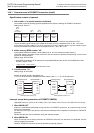
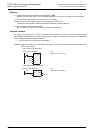
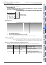
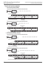
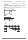
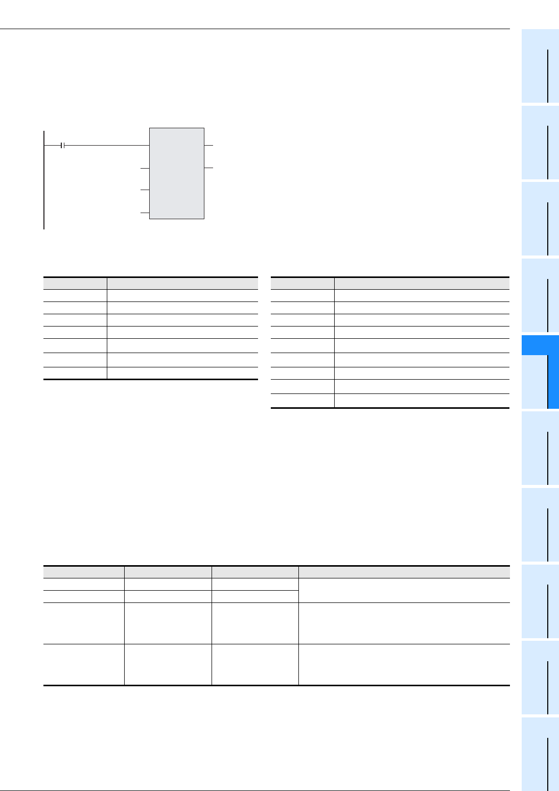
Command input
RS
EN
s
m
ENO
d
n
Number of bytes
to be received
Head device storing
data to be sent
Number of bytes of
data to be sent
Head device storing
received data when
receiving is completed