16 Applied Instructions (External Device)
16.6 RMRD / Read from F2-32RM
427
FXCPU Structured Programming Manual
[Basic & Applied Instruction]
11
Applied Instructions
(Data Operation)
12
Applied Instructions
(High Speed
Processing)
13
Applied Instructions
(Handy
Instruction)
14
Applied Instructions
(External FX I/O
Device)
15
Applied Instructions
(External Device
(optional device))
16
Applied Instructions
(External Device)
17
Applied Instructions
(Data Transfer 2)
18
Applied Instructions
(Floating Point)
19
Applied Instructions
(Data Operation 2)
20
Applied Instructions
(Positioning
Control)
16.6 RMRD / Read from F2-32RM
Outline
This instruction reads out the ON/OFF state of output of the F2-32RM type programmable cam switch to the
PLC.
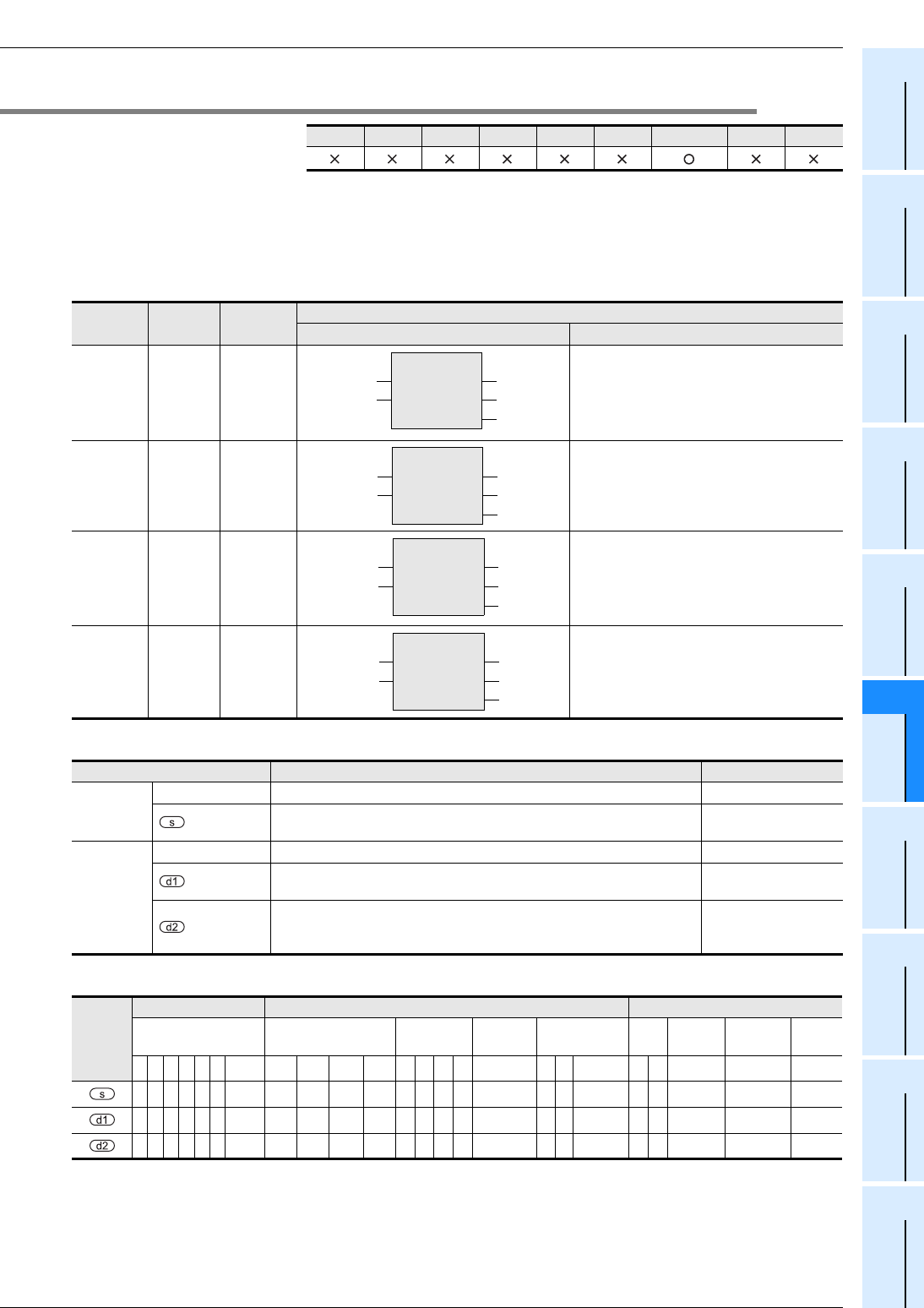
1. Format and operation, execution form
2. Set data
3. Applicable devices
FX3U(C) FX3G(C) FX3S FX2N(C) FX1N(C) FX1S FXU/FX2C FX0N FX0(S)
Instruction
name
Operation
Execution
form
Expression in each language
Structured ladder/FBD ST
RMRD 16 bits Continuous RMRD(EN, s, d1, d2);
RMRDP 16 bits Pulse RMRDP(EN, s, d1, d2);
DRMRD 32 bits Continuous DRMRD(EN, s, d1, d2);
DRMRDP 32 bits Pulse DRMRDP(EN, s, d1, d2);
Variable Description Data type
Input
variable
EN Execution condition Bit
Head input number of FX
2-24EI connected to F2-32RM (16 points
occupied)
Bit
Output
variable
ENO Execution state Bit
Head output number of FX
2-24EI connected to F2-32RM (8 points
occupied)
Bit
Bit device for storing output status (ON/OFF).
• 16-bit operation: 16 points occupied
• 32-bit operation: 32 points occupied
Bit
Operand
type
Bit Devices Word Devices Others
System user Digit designation
System
user
Special
unit
Index
Con
stant
Real
Number
Character
String
Pointer
XYMTCS
D.b
KnX KnY KnM KnS T C D R
U\G
V Z Modifier K H E
""
P
z
z
zz z z
RMRD
EN
s
ENO
d1
d2
RMRDP
EN
s
ENO
d1
d2
DRMRD
EN
s
ENO
d1
d2
DRMRDP
EN
s
ENO
d1
d2


