


30 Applied Instructions (External Device Communication)
30.4 IVWR / Inverter Parameter Write
717
FXCPU Structured Programming Manual
[Basic & Applied Instruction]
21
Applied Instructions
(Real Time
Clock Control)
22
Applied Instructions
(External Device)
23
Applied Instructions
(Extension
Function)
24
Applied Instructions
(Others)
25
Applied Instructions
(Block Data
Operation)
26
Applied Instructions
(Character
String Control)
27
Applied Instructions
(Data Operation 3)
28
Applied Instructions
(Data Comparison)
29
Applied Instructions
(Data Table
Operation)
30
Applied Instructions
(External Device
Communication)
Function and operation explanation
→ For detailed explanation of the instruction, refer to the Data Communication Edition manual.
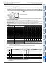
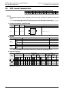
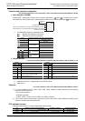
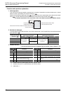
1. 16-bit operation (IVWR)
A value specified in the device specified by is written to a parameter in the device specified by in
an inverter connected to a communication port n whose station number is in the device specified by .
*1. Mitsubishi Electric's FREQROL - F700, A700, E700, D700, V500, F500, A500, E500 and S500 series
general purpose inverters
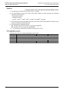
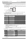
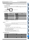
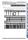
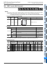
2. Related devices
→ For the instruction execution complete flag use method, refer to Section 1.3.4.
*1. Cleared when PLC power supply is turned from OFF to ON.
*2. Cleared when the PLC mode switches from STOP to RUN.
*3. Initial value: -1
Cautions
→ For other cautions, refer to the Data Communication Edition manual.
1) The instruction is provided in the FX
3G PLC Ver. 1.10 or later.
2) It is not permitted to use an "IVCK, IVDR, IVRD, IVWR, IVBWR
*1
or IVMC" instruction and a following
instruction for the same port:
- "RS or RS2" instruction
- "ADPRW" instruction
-"FLCRT
*1
, FLDEL
*1
, FLWR
*1
, FLRD
*1
, FLCMD
*1
or FLSTRD
*1
" instruction
3) Two or more inverter communication instructions (IVCK, IVDR, IVRD, IVWR, IVBWR
*1
and IVMC) can be
driven for the same port at the same time.
4) Cautions on using the password function in the D700 Series.
a) When a communication error occurs
When a communication error occurs in an inverter communication instruction, the FX PLC
automatically retries communication up to 3 times
*2
.
Accordingly, note that the number of times of password reset error displayed in accordance with the
setting of Pr297 may not agree with the actual number of times of password input error as described
below when a password reset error occurs in the D700 Series in which "display of the number of times
of password reset error"
*3
is made valid using Pr297.
Do not execute automatic retry (re-driving of an inverter instruction) using a sequence program when
writing data to Pr297.
Number
Description
Number
Description
ch1 ch2 ch1 ch2
M8029 Instruction execution complete D8063 D8438
Error code of serial communication error*
1
M8063 M8438
Serial communication error*
1
D8150 D8155
Response wait time in inverter communication*
1
M8151 M8156
Inverter communicating
D8151 D8156
Step number in inverter communication*
3
M8152 M8157
Inverter communication error*
2
D8152 D8157
Error code of inverter communication error*
2
M8153 M8158
Inverter communication error latch*
2
D8153 D8158
Latch of inverter communication error occurrence
step
*2*3
M8154 M8159
IVBWR instruction error*
2
D8154 D8159
IVBWR instruction error parameter number
*2*3
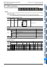
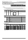
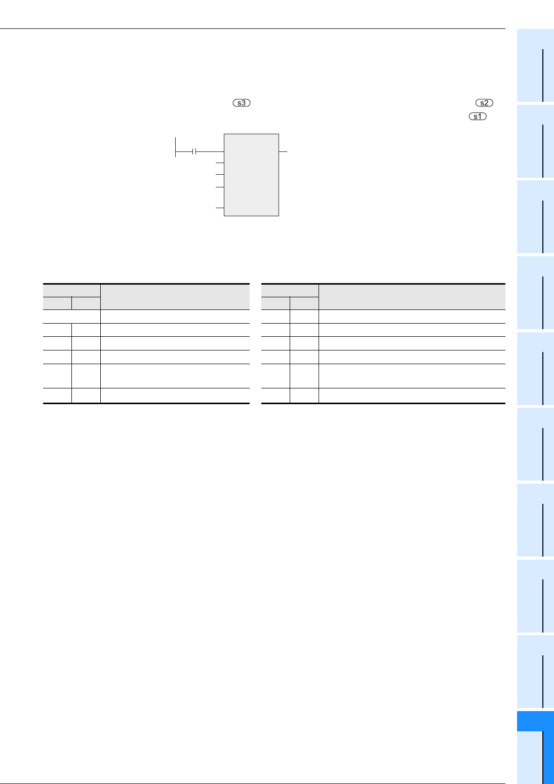
IVWR
EN ENO
s1
s2
s3
n
Channel to be used
Command
input
Inverter station number
Inverter parameter number
Set value to be written to the inverter parameter
or device storing the data to be set