


14 Applied Instructions (External FX I/O Device)
14.5 SEGL / Seven Segment With Latch
371
FXCPU Structured Programming Manual
[Basic & Applied Instruction]
11
Applied Instructions
(Data Operation)
12
Applied Instructions
(High Speed
Processing)
13
Applied Instructions
(Handy
Instruction)
14
Applied Instructions
(External FX I/O
Device)
15
Applied Instructions
(External Device
(optional device))
16
Applied Instructions
(External Device)
17
Applied Instructions
(Data Transfer 2)
18
Applied Instructions
(Floating Point)
19
Applied Instructions
(Data Operation 2)
20
Applied Instructions
(Positioning
Control)
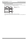
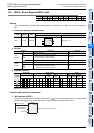
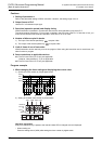
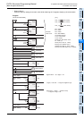
2) Strobe signal
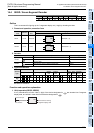
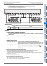
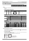
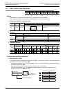
4. Selection of parameter n
Select by referring to the table below depending on the positive or negative logic of the PLC side, and the
positive or negative logic of the 7-segment display side.
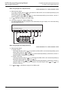
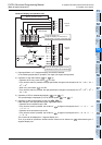
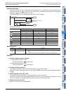
5. Explanation of selection method of parameter n by exemplary cases
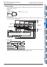
When the following 7-segment display is connected, n=1 in the case of 4 digits × 1 set, and n=5 in the case of
4 digits × 2 sets.
1) Transistor output of PLC
- Sync output = negative logic
- Source output = positive logic
2) 7-segment display
- Data input = negative logic
- Strobe signal = positive logic
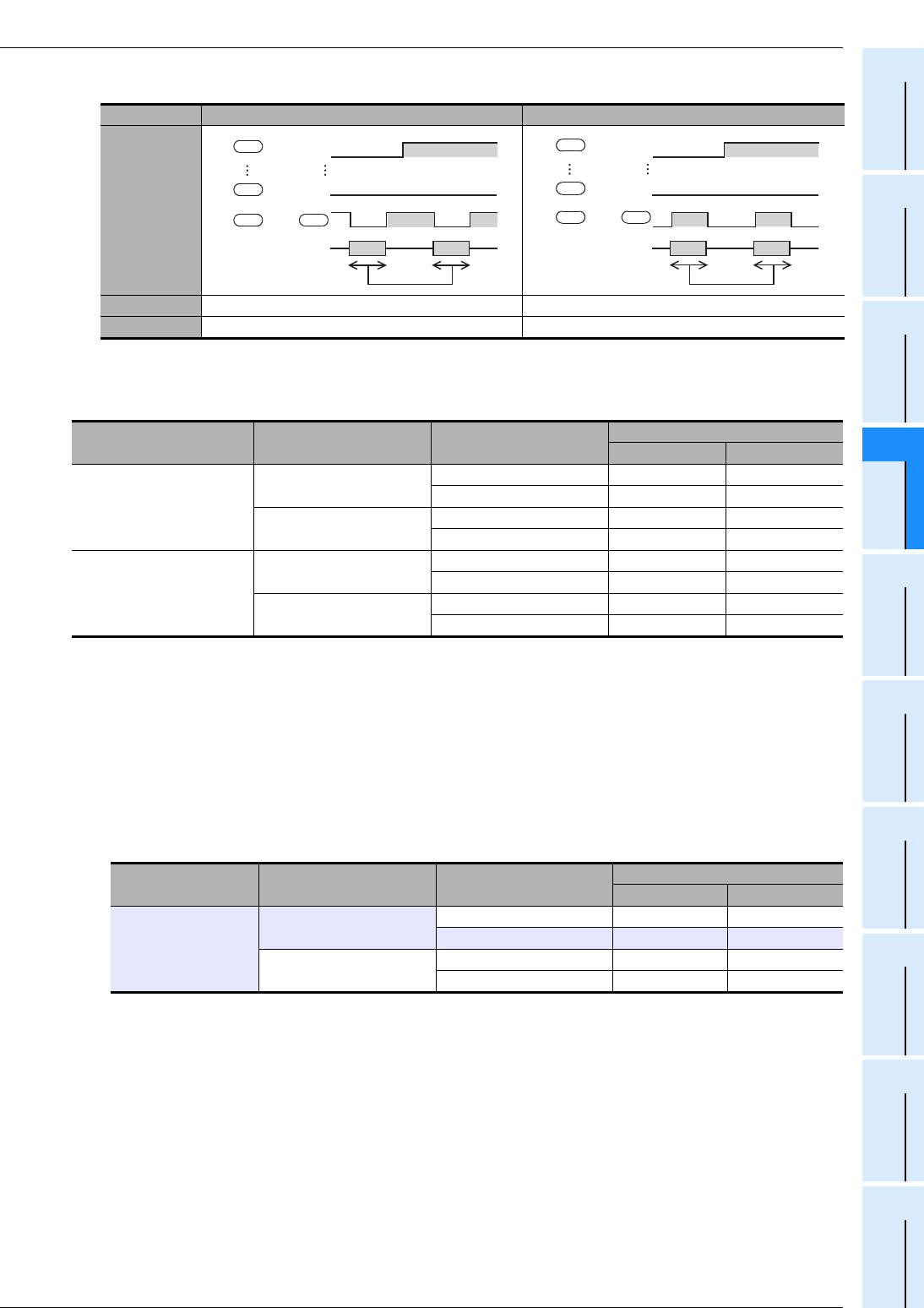
Logic Negative logic Positive logic
Timing chart
Explanation Data latched at LOW level is held Data latched at HIGH level is held
Logic check
PLC output logic Data input Strobe signal
Parameter n
4 digits × 1 set 4 digits × 2 sets
Negative logic
Negative logic (coinciding)
Negative logic (coinciding) 0 4
Positive logic (not coinciding) 1 5
Positive logic (not coinciding)
Negative logic (coinciding) 2 6
Positive logic (not coinciding) 3 7
Positive logic
Positive logic (coinciding)
Positive logic (coinciding) 0 4
Negative logic (not coinciding) 1 5
Negative logic (not coinciding)
Positive logic (coinciding) 2 6
Negative logic (not coinciding) 3 7
PLC output logic Data input Strobe signal
Parameter n
4 digits × 1 set 4 digits × 2 sets
Negative logic
Negative logic (coinciding)
Negative logic (coinciding) 0 4
Positive logic (not coinciding) 1 5
Positive logic (not coinciding)
Negative logic (coinciding) 2 6
Positive logic (not coinciding) 3 7
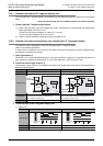
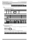
H
Strobe display
change
Latch
None None
HLHL
+4 to
1
8+3
d
d
d d
+7
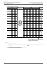
H
H
+4 to
H
Strobe display
change
1
8
Latch
None None
+3
d
d
d d
+7