


20 Applied Instructions (Positioning Control)
20.8 DRVA / Drive to Absolute
539
FXCPU Structured Programming Manual
[Basic & Applied Instruction]
11
Applied Instructions
(Data Operation)
12
Applied Instructions
(High Speed
Processing)
13
Applied Instructions
(Handy
Instruction)
14
Applied Instructions
(External FX I/O
Device)
15
Applied Instructions
(External Device
(optional device))
16
Applied Instructions
(External Device)
17
Applied Instructions
(Data Transfer 2)
18
Applied Instructions
(Floating Point)
19
Applied Instructions
(Data Operation 2)
20
Applied Instructions
(Positioning
Control)
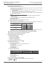
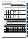
S2: <FX3S, FX3G, FX3GC, FX3U, FX3UC PLCs>
When high speed output special adapter is used at the pulse output destination in the FX
3U PLC,
as the rotating direction signal, use the output shown in the table below.
When built-in transistor output is used at the pulse output destination in the FX
3S, FX3G, FX3GC,
FX
3U and FX3UC PLCs, as the rotating direction signal, use the transistor output.
S3: The FX
3U and FX3UC PLCs only are applicable, index (V, Z) decoration is disabled.
S4: The FX
3G, FX3GC, FX3U and FX3UC PLCs only are applicable.
S5: The FX
3U and FX3UC PLCs only are applicable.
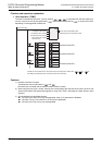
3) Number of output pulses is specified by .
The setting range is as follows.
a) In the case of 16-bit operation
• In the case of FX
3S, FX3G, FX3GC, FX3U and FX3UC PLCs
-32,768 to +32,767
• In the case of FX
1S, FX1N and FX1NC PLCs
-32,768 to +32,767
b) In the case of 32-bit operation
• In the case of FX
3S, FX3G, FX3GC, FX3U and FX3UC PLCs
-999,999 to +999,999
• In the case of FX
1S, FX1N and FX1NC PLCs
-999,999 to +999,999
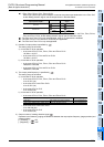
4) The output pulse frequency is specified by .
The setting range is as follows.
a) In the case of 16-bit operation
• In the case of FX
3S, FX3G, FX3GC, FX3U and FX3UC PLCs
10 to 32,767 (Hz)
• In the case of FX
1S and FX1N PLCs
10 to 32,767 (Hz)
• In the case of FX
1NC PLC
10 to 10,000 (Hz)
b) In the case of 32-bit operation
• In the case of FX
3S, FX3G, FX3GC, FX3U and FX3UC PLCs
• In the case of FX
1S and FX1N PLCs
10 to 100,000 (Hz)
• In the case of FX
1NC PLC
10 to 10,000 (Hz)
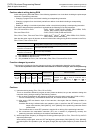
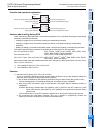
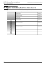
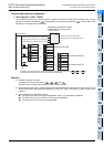
5) Output number of rotating direction signal
Operation is as follows by judging the difference between the output pulse frequency (target position) and
present position.
[+ (Positive)] → : ON
[- (Negative)] → : OFF
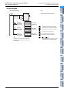
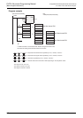
Connection position of high speed
output special adapter
Pulse output
Rotating direction
signal
First unit
=Y000
=Y004
=Y001 =Y005
Second unit
=Y002 =Y006
=Y003 =Y007
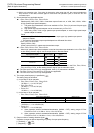
Pulse output destination Setting range
FX
3U PLC High speed output special adapter 10 to 200,000 (HZ)
FX3S, FX3G, FX3GC, FX3U, FX3UC PLCs Basic unit (transistor output) 10 to 100,000 (HZ)