


12 Applied Instructions (High Speed Processing)
260
FXCPU Structured Programming Manual
[Basic & Applied Instruction]
12.2 REFF / Refresh and Filter Adjust
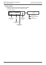
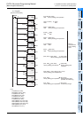
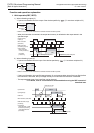
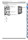
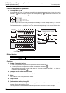
• When the input turns ON "n × 1 ms" before the instruction is executed, the input image memory is set to
ON. When the input turns OFF "n × 1 ms" before the instruction is executed, the input image memory is set
to OFF.
• When the command input is ON, the REFF instruction is executed in each operation cycle.
• When the command input is OFF, the REFF instruction is not executed, and the input filter uses the set
value of D8020 (which is the value used during input processing).
Cautions
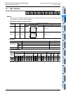
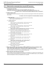
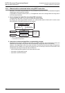
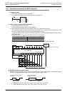
1. Function of the input filter
The filter time of the digital filter can be changed in 1 ms units within the range from 0 to 60 ms using
instructions. When the filter time is set to "0", the input filter value is as follows.
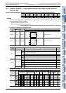
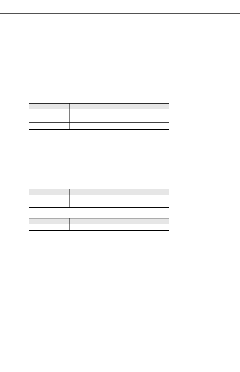
1) For FX
3U and FX3UC PLCs
*1. X000 to X007 in the FX
3U-16M, and FX3UC-16M
*2. When setting the input filter time to "5 μs", perform the following actions.
- Make sure that the wiring length is 5 m or less.
- Connect a bleeder resistor of 1.5 kΩ (1 W or more) to the input terminal, and make sure that the load current in the
open collector transistor output of the external equipment is 20 mA or more including the input current of the main
unit.
*3. The filter time is fixed for 10 ms in X010 to X017 in 16-point type FX3U PLCs and 16-point type FX3UC
PLCs.
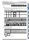
2) For FX
2N and FX2NC PLCs
3) For FX
U and FX2C PLCs
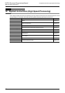
2. Some restrictions to applicable devices
S1: The FX3U and FX3UC PLCs only are applicable.
S2: Set the filter time within the range of K0(H0) to K60(H3C) [0 to 60 ms].
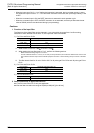
Input number Input filter value when set to "0"
X000 to X005
5μs
*2
X006, X007
50μs
X010 to X017
*3
200μs
*3
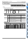
Input number Input filter value when set to "0"
X000, X001
20μs
X002 to X017
50μs
Input number Input filter value when set to "0"
X000 to X007
50
μs