


29 Applied Instructions (Data Table Operation)
29.4 SCL / Scaling (Coordinate by Point Data)
693
FXCPU Structured Programming Manual
[Basic & Applied Instruction]
21
Applied Instructions
(Real Time
Clock Control)
22
Applied Instructions
(External Device)
23
Applied Instructions
(Extension
Function)
24
Applied Instructions
(Others)
25
Applied Instructions
(Block Data
Operation)
26
Applied Instructions
(Character
String Control)
27
Applied Instructions
(Data Operation 3)
28
Applied Instructions
(Data Comparison)
29
Applied Instructions
(Data Table
Operation)
30
Applied Instructions
(External Device
Communication)
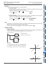
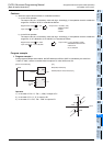
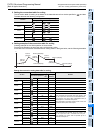
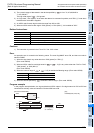
3. Setting the conversion table for scaling
The conversion table for scaling is set based on the data table stored in a device specified in and later.
The data table has the following configuration:
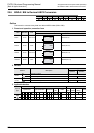
4. Setting example of the conversion table for scaling
A setting example for the 16-bit operation is shown below.
For the 32-bit operation, set each item using a 32-bit binary value.
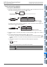
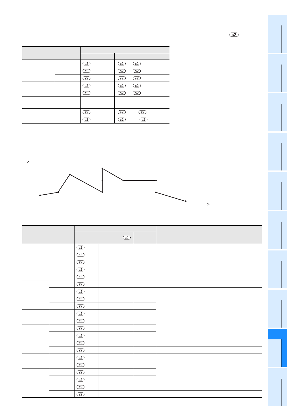
In the case of the conversion characteristics for scaling shown in the figure below, set the following data table.
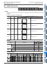
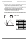
Setting the conversion setting data table for scaling
Set item
Device assignment in setting data table
16-bit operation 32-bit operation
Number of coordinate points
[+1,]
Point 1
X coordinate
+1 [ +3, +2]
Y coordinate
+2 [ +5, +4]
Point 2
X coordinate
+3 [ +7, +6]
Y coordinate
+4 [ +9, +8]
...
...
...
...
Point n (last)
X coordinate
+2n-1 [ +4n-1, +4n-2]
Y coordinate
+2n [ +4n+1, +4n]
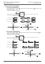
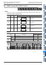
Set item
Setting device and setting contents
Remarks
When R0 is specified in
Setting
contents
Number of coordinate points R0 K10
Point 1
X coordinate
+1
R1 K5
Y coordinate
+2
R2 K7
Point 2
X coordinate
+3
R3 K20
Y coordinate
+4
R4 K30
Point 3
X coordinate
+5
R5 K50
Y coordinate
+6
R6 K100
Point 4
X coordinate
+7
R7 K200
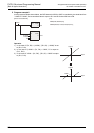
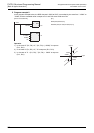
When coordinates are specified using three points in this
way, the output value can be set to an intermediate value.
In this example, the output value (intermediate value) is
specified by the Y coordinate of the point 5.
If the x coordinate is the same at three points or more, the
value at the second point is also output.
Y coordinate
+8
R8 K25
Point 5
X coordinate
+9
R9 K200
Y coordinate
+10
R10 K70
Point 6
X coordinate
+11
R11 K200
Y coordinate
+12
R12 K250
Point 7
X coordinate
+13
R13 K250
Y coordinate
+14
R14 K90
Point 8
X coordinate
+15
R15 K350
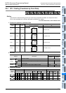
When coordinates are specified using two points in this
way, the output value is the Y coordinate at the next point.
In this example, the output value is specified by the Y
coordinate of the point 9.
Y coordinate
+16
R16 K90
Point 9
X coordinate
+17
R17 K350
Y coordinate
+18
R18 K30
Point 10
X coordinate
+19
R19 K400
Y coordinate
+20
R20 K7
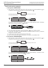
Point 1 (5,7)
X
Y
Point 2
(20,30)
Point 3
(50,100)
Point 5
(200,70)
Point 4 (200,25)
Point 6 (200,250)
Point 7
(250,90)
Point 8 (350,90)
Point 9
(350,30)
Point 10 (400,7)