


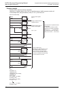


15 Applied Instructions (External Device (optional device))
15.9 PID / PID Control Loop
416
FXCPU Structured Programming Manual
[Basic & Applied Instruction]
*1. + 20 to + 24 will be occupied in the case of bit1 = 1, bit2 = 1, or bit5 = 1 of + 1 action setting
(ACT)
*2. FX
2N, FX2NC, FX1N, FX1NC, FX1S, FXU, FX2C PLCs are not usable.
Cautions
1. Cautions when using a plurality of instructions
Possible to execute plural times simultaneously (the number of loops is not limited), but you must be careful
so that the device numbers may not be overlapped in the devices used in or used in operation.
2. Number of parameters occupied
1) In the case of limit cycle method
- Devices are occupied by 29 points from the head device specified by .
2) In the case of step response method
- Action setting (ACT) setting: when all of bit1, bit2, bit5 are other than "0"
Devices are occupied by 25 points from the head device specified by .
- Action setting (ACT) setting: when all of bit1, bit2, bit5 are "0"
Devices are occupied by 20 points from the head device specified by .
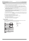
3. When specifying a device in power failure hold region
As for the output value (MV) of PID instruction, specify the data register excluding the power failure hold
region.
(When specifying the data register in the power failure hold region, you must clear the content of backup while
the PLC is ON by the following program.)
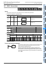
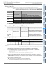
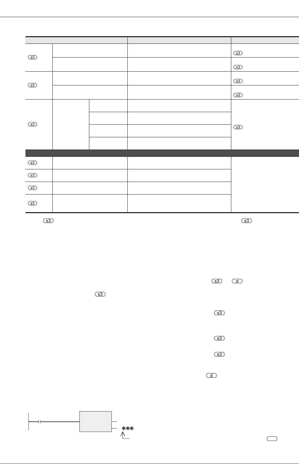
Setting items Content of setting Remarks
+22
*1
Output change amount (increase
side) alarm setting value
0 to 32767
Direction of action (ACT):
+1 bit2 = 1, bit5 = 0; valid
Output upper limit setting value -32768 to 32767
Direction of action (ACT):
+1 bit2 = 0, bit5 = 1; valid
+23
*1
Output change amount (decrease
side) alarm setting value
0 to 32767
Direction of action (ACT):
+1 bit2 = 1, bit5 = 0; valid
Output lower limit setting value -32768 to 32767
Direction of action (ACT):
+1 bit2 = 0, bit5 = 1; valid
+24
*1
Alarm output
bit0
0: Input change amount (increase side) not over
1: Input change amount (increase side) over
Direction of action (ACT):
+1 bit1 = 1 or bit2 = 1; valid
bit1
0: Input change amount (decrease side) not over
1: Input change amount (decrease side) over
bit2
0: Output change amount (increase side) not over
1: Output change amount (increase side) over
bit3
0: Output change amount (decrease side) not over
1: Output change amount (decrease side) over
The following setting is required when using the limit cycle method (in the case of action direction (ACT) b6: ON).
+25
*2
PV value threshold (hysteresis)
width (SHPV)
To be set according to fluctuation of measured
value (PV).
Action setting (ACT) b6:
Occupied when limit cycle
method (ON) is selected.
+26
*2
Output value upper limit (ULV)
Setting of maximum output value (ULV) of output
value (MV)
+27
*2
Output value lower limit (LLV)
Setting of minimum output value (LLV) of output
value (MV)
+28
*2
Weight setting parameter from end
of tuning cycle to start of PID control
(KW)
-50 to 32717%
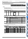
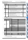
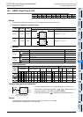
d
M8002
Initial pulse
Program example
Data register number of battery backup region specified by
RST
EN ENO
d
D