


35 Interrupt Function and Pulse Catch Function
811
FXCPU Structured Programming Manual
[Basic & Applied Instruction]
31
Applied Instructions
(Data Transfer 3)
32
Applied Instructions
(High Speed
Processing 2)
33
Applied Instructions
(Extension File
Register Control)
34
Applied Instructions
(FX
3U
-CF-ADP)
35
Interrupt Function
and Pulse Catch
Function
A
Relationships
between devices
and addresses
B
Applied
Instruction List
35.7 Pulse Catch Function[M8170 to M8177]
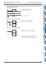
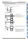
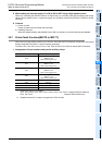
5. When setting an interrupt output (Y or M) to ON or OFF using a high speed counter
When only controlling the ON/OFF status of an output relay (Y) or auxiliary relay (M) according to the current
value of a high speed counter, a required program can be easily created using DHSCS, DHSCR or DHSZ
instruction.
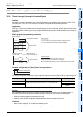
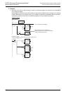
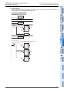
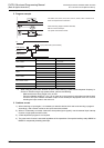
6. Cautions
1) Pointer number
Pointer numbers cannot overlap with each other.
2) Disabling interrupts
When the special auxiliary relay M8059 is set to ON in a program, all counter interrupts are disabled.
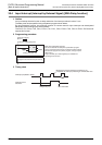
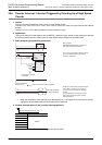
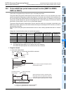
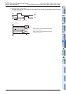
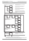
35.7 Pulse Catch Function[M8170 to M8177]
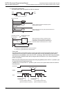
When the input relay X000 to X007 turns ON from OFF after the EI instruction is executed, the special
auxiliary relay M8170 to M8177 is set for interrupt processing.
The FX
0S, FX0, FX0N, FX1S, FX1N, FX1NC, FX3S, FX3G or FX3GC PLC does not require the EI instruction.
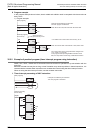
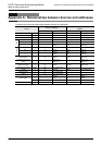
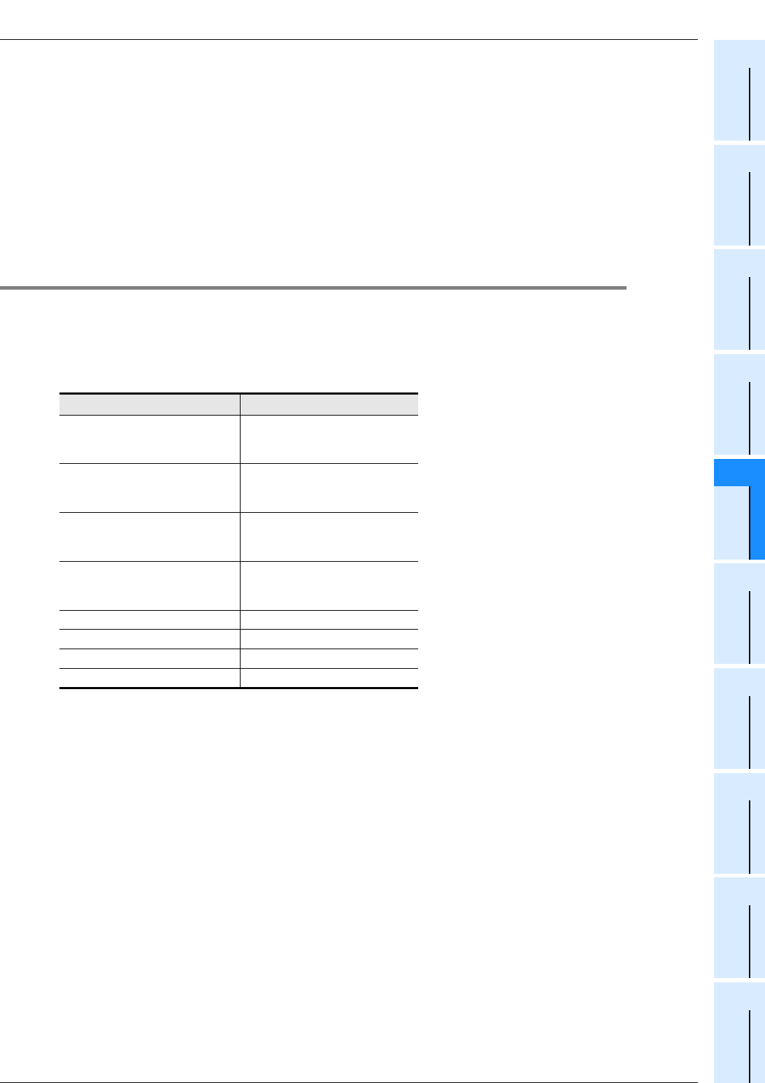
1. Assignment of input numbers and special auxiliary relays
*1. Differs from one PLC to another.
FX
1S, FX1N, FX1NC, FXU, FX2C, FX2N, FX2NC, FX3S, FX3G, FX3GC: Supports X000 to X005 only.
FX
0S, FX0, FX0N : Supports X000 to X003 only.
*2. Cleared when the PLC mode is changed from STOP to RUN.
Pulse catch input
*1
Pulse catch relay
X000
M8170
*2
(M8065
*2
in the
FX0S, FX0 and FX0N PLCs)
X001
M8171
*2
(M8057
*2
in the
FX0S, FX0 and FX0N PLCs)
X002
M8172
*2
(M8058
*2
in the
FX0S, FX0 and FX0N PLCs)
X003
M8173
*2
(M8059
*2
in the
FX0S, FX0 and FX0N PLCs)
X004
M8174
*2
X005
M8175
*2
X006
M8176
*2
X007
M8177
*2