


11 Applied Instructions (Data Operation)
11.1 ZRST / Zone Reset
227
FXCPU Structured Programming Manual
[Basic & Applied Instruction]
11
Applied Instructions
(Data Operation)
12
Applied Instructions
(High Speed
Processing)
13
Applied Instructions
(Handy
Instruction)
14
Applied Instructions
(External FX I/O
Device)
15
Applied Instructions
(External Device
(optional device))
16
Applied Instructions
(External Device)
17
Applied Instructions
(Data Transfer 2)
18
Applied Instructions
(Floating Point)
19
Applied Instructions
(Data Operation 2)
20
Applied Instructions
(Positioning
Control)
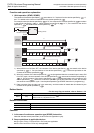
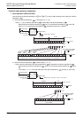
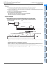
2. FMOV
FMOV instruction is provided to write a constant (example: K0) at one time. By using this instruction, "0" can
be written to word devices (KnY, KnM, KnS, T, C, D and R) at one time.
Cautions
1) Instructions of pulse operation type are not provided in the FX0S, FX0 or FX0N PLC.
To execute pulse operation, make the instruction execution condition pulse type.
2) Specify same type of devices in the devices specified by and . The device number of the device
specified by should be smaller than or equal to the device number of the device specified by .
If the device number of the device specified by is larger than the device number of the device
specified by , only one device specified by is reset.
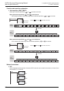
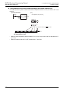
3) When specifying the high-speed counter, ZRST instruction is handled as the 16-bit type, but 32-bit
counters can be specified in and .
However, it is not possible to specify a 16-bit counter in the device specified by and specify a 32-bit
counter in the device specified by ; and should be a same type.
Program example
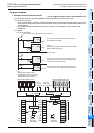
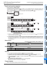
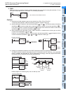
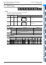
4) Caution for simultaneous instances of the ZRST instruction and the PLS instruction
The ZRST instruction resets the last stage for the PLS instruction and PLF instruction of the applicable
device. In addition, the reset state of T and C is also reset. Accordingly, when the program shown below
is executed, the PLS instruction continuously sets M0 to ON.
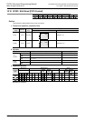
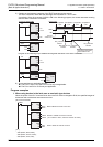
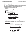
Please program in the following way to turn on M0 only once.
K0 is written to D0 to D99 at one time.
X002
K0 D0
FMOV
EN
s
n
ENO
d
K100
16-bit counter
Command input
CN230
ZRST
EN ENO
d1
d2
CN180
32-bit counter
Command input
CN199
ZRST
EN ENO
d1
d2
CN180
CN230
ZRST
EN ENO
d1
d2
CN200
Timing chart
Structured ladder/FBD
X000
M0
ZRST instruction
execution
one operation cycle one operation cycle
M0
X000
M0
M0
M100
ZRST
EN ENO
d1
d2
PLS
EN ENO
ZRST instruction
execution
PLS instruction
execution
PLS instruction
execution
d
Structured ladder/FBD
M0
X000
M0
M100
ZRST
EN ENO
d1
d2
M0
MEP
EN ENO