


31 Applied Instructions (Data Transfer 3)
31.1 RBFM / Divided BFM Read
731
FXCPU Structured Programming Manual
[Basic & Applied Instruction]
31
Applied Instructions
(Data Transfer 3)
32
Applied Instructions
(High Speed
Processing 2)
33
Applied Instructions
(Extension File
Register Control)
34
Applied Instructions
(FX
3U
-CF-ADP)
35
Interrupt Function
and Pulse Catch
Function
A
Relationships
between devices
and addresses
B
Applied
Instruction List
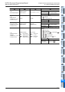
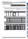
31.1.1 Common items between RBFM instruction and WBFM instruction
Specification of unit number of special function block and unit and buffer memory
→ For the connection method of special extension units and blocks, number of connectable units and
blocks, and handling of I/O numbers, refer to the manual of the PLC used and special function block
and unit.
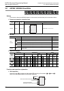
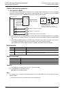
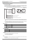
1. Unit number "m1" of a special extension unit and block
Use the unit number to specify to which equipment the RBFM and/or WBFM instruction works.
Setting range: K0 to K7
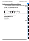
A unit number is automatically assigned to each special extension unit and block connected to the PLC.
The unit number is assigned in the way "No. 0 → No. 1 → No. 2 ..." starting from the equipment nearest to the
main unit.
Since the FX
3UC-32MT-LT(-2) PLC has a built-in CC-Link/LT master, the unit number is given "No. 1 → No. 2
→ No. 3 ..." from the equipment nearest to the main unit.
2. Buffer memory (BFM) number "m2"
Up to 32767 16-bit RAM memories are built in a special extension unit and block, and they are called buffer
memories (BFM).
The buffer memory number is from "0" to "32766", and the contents are determined according to each special
function unit and block.
Setting range: K0 to K32766
→ For the contents of buffer memories, refer to the manual of the special function block and unit
used.
Unit
No.0
Built-in CC-Link/LT
Unit
No.1
Unit
No.2
Unit
No.3
FX
3UC
-32MT-LT(-2)
Main unit
I/O
extension
block
Special
extension
block
Special
extension
block
Special
extension
block
I/O
extension
block