


5 Basic Instruction
5.2 LDP, LDF, ANDP, ANDF, ORP, ORF
60
FXCPU Structured Programming Manual
[Basic & Applied Instruction]
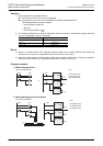
5. Differences in the operation caused by auxiliary relay (M) numbers
Not supported by the FX1S, FX1N or FX1NC PLC.
When an auxiliary relay (M) is specified as a device in LDP, LDF, ANDP, ANDF, ORP and ORF instructions,
the operation varies depending on the device number range as shown in the figure below.
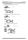
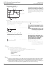
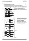
<M0 to M2799, M3072 to M7679> (M0 to M2799 for the FX
2N
and FX
2NC
PLCs, M0 to M1535 for the FX
3S
PLC)
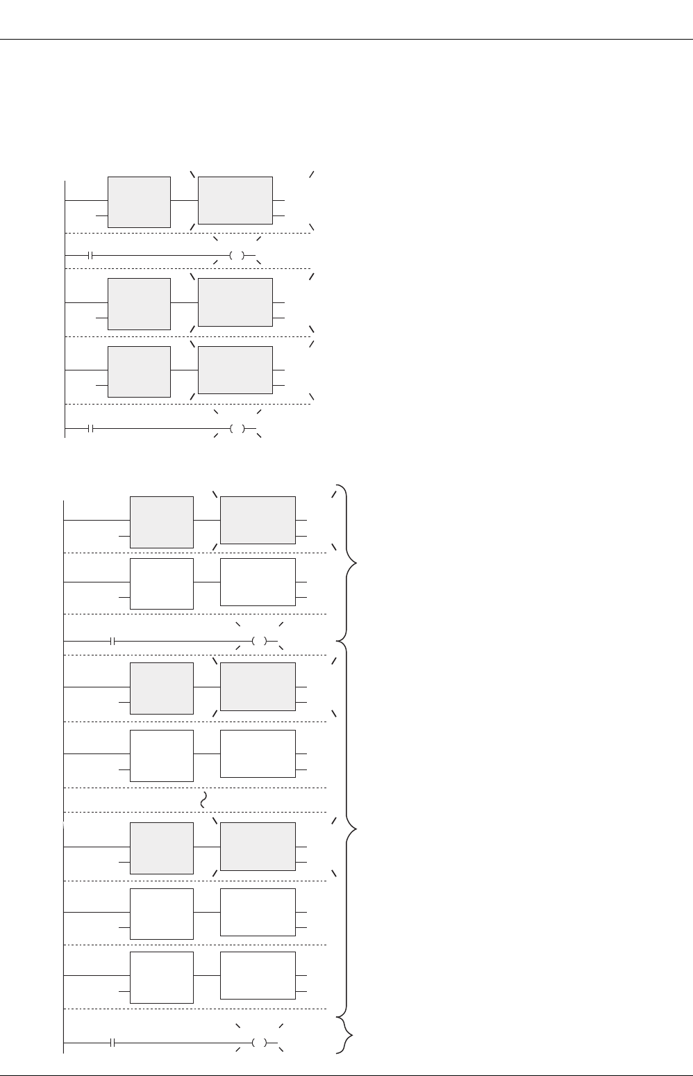
After M0 is driven by X000, all contacts 1) to 4) corresponding
to M0 are activated.
• The contacts 1) to 3) detect the rising edge of M0.
• Because of LD instruction, the contact 4) is conductive while
M0 is ON.
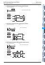
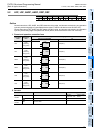
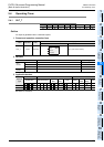
<M2800 to M3071>
From M2800 driven by X000, the program is
divided into the upper block (block A) and the
lower block (block B). In each of the blocks A
and B, only the first contact which detects the
rising or falling edge is activated.
Because of LD instruction, the contact in the
block C is conductive while M2800 is ON.
By utilizing these characteristics, "transition
of state by same signal" in a step ladder
circuit can be efficiently programmed.
X000
M0
M0
M0
1)
2)
3)
4)
M0
M0
LDP
EN
s
ENO
SET
EN ENO
d
M50
LDP
EN
s
ENO
SET
EN ENO
d
M51
LDP
EN
s
ENO
SET
EN ENO
d
M52
M53
Block B
X000
M2800
M2800
M2800
M2800
M2800
LDP
EN
s
ENO
SET
EN ENO
d
M1
LDP
EN
s
ENO
SET
EN ENO
d
M2
LDP
EN
s
ENO
SET
EN ENO
d
M3
M7
M2800
LDP
EN
s
ENO
SET
EN ENO
d
M0
M2800
M2800
LDF
EN
s
ENO
SET
EN ENO
d
M4
LDP
EN
s
ENO
SET
EN ENO
d
M5
M2800
LDF
EN
s
ENO
SET
EN ENO
d
M6
Block A
Block C