


13 Applied Instructions (Handy Instruction)
13.9 ROTC / Rotary Table Control
347
FXCPU Structured Programming Manual
[Basic & Applied Instruction]
11
Applied Instructions
(Data Operation)
12
Applied Instructions
(High Speed
Processing)
13
Applied Instructions
(Handy
Instruction)
14
Applied Instructions
(External FX I/O
Device)
15
Applied Instructions
(External Device
(optional device))
16
Applied Instructions
(External Device)
17
Applied Instructions
(Data Transfer 2)
18
Applied Instructions
(Floating Point)
19
Applied Instructions
(Data Operation 2)
20
Applied Instructions
(Positioning
Control)
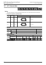
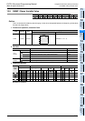
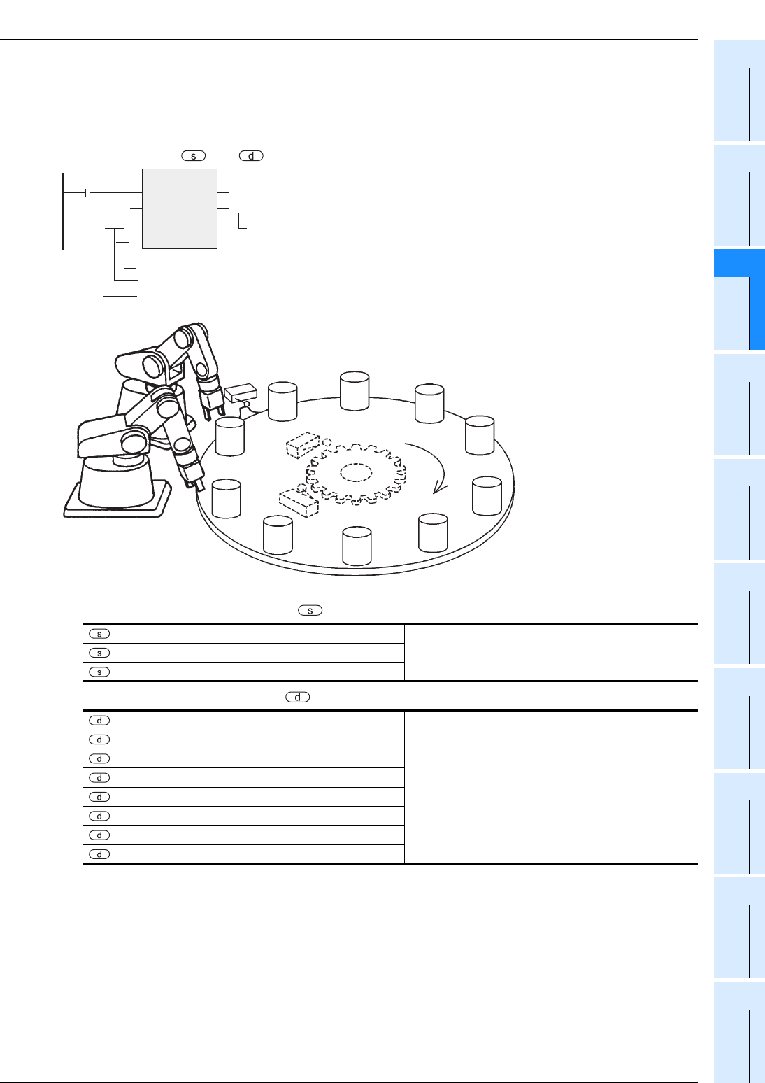
Function and operation explanation
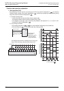
1. 16-bit operation(ROTC)
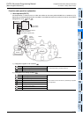
As shown below, in order to put on or take out articles on the rotary table divided into m1 sections (=10),
depending on the demanding window, the table is controlled and moved by a shortcut route in the condition
designated in m2 or and .
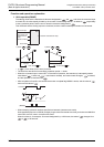
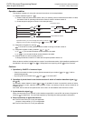
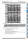
1) Designation register of call condition
2) Designation bit of calling condition
Register for counting
To be set preliminarily by transfer command
+1
Setting of calling window number
+2
Setting of calling article number
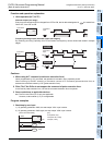
:
Phase A signal
Internal contact circuit to be driven is preliminarily composed
of input signal (X).
+1
Phase B signal
+2
0 point detection signal
+3
High speed normal rotation
+4
Low speed normal rotation
+5
Stop
+6
Low speed reverse rotation
+7
High speed reverse rotation
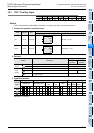
Command
ROTC
EN
s
m1
ENO
d
m2
D200
K10
K2
M0
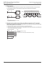
Call condition
register (bits)
Number of low speed sections
Number of divisions
Call condition register (bits)
9
X000(M0)
8
7
6
5
4
3
2
1
Normal
rotation
0
Rotary table
X001(M1)
0 point
detection
X002(M2)
Detection
switch
Article
Window 1