


15 Applied Instructions (External Device (optional device))
15.9 PID / PID Control Loop
415
FXCPU Structured Programming Manual
[Basic & Applied Instruction]
11
Applied Instructions
(Data Operation)
12
Applied Instructions
(High Speed
Processing)
13
Applied Instructions
(Handy
Instruction)
14
Applied Instructions
(External FX I/O
Device)
15
Applied Instructions
(External Device
(optional device))
16
Applied Instructions
(External Device)
17
Applied Instructions
(Data Transfer 2)
18
Applied Instructions
(Floating Point)
19
Applied Instructions
(Data Operation 2)
20
Applied Instructions
(Positioning
Control)
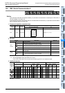
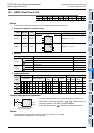
2. Setting items
*1. When the auto-tuning is not used, the same number of points as in the step response method are
occupied.
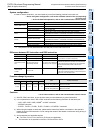
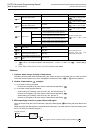
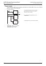
3. List of parameters to +28
*1. + 20 to + 24 will be occupied in the case of bit1 = 1, bit2 = 1, or bit5 = 1 of + 1 action setting
(ACT)
*2. FXU, FX2C PLCs are not usable.
*3. FX
1S, FX1N, FX1NC, FX2N, FX2NC PLCs are not usable.
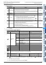
Setting items Content
No. of points
occupied
Target value(SV)
• To set the target value (SV).
• PID instruction does not change the contents of setting.
• Cautions when using auto-tuning (limit cycle method)
If the target value for auto-tuning and the target value for PID control are different, the
value to which the bias value is added is set, and the actual target value must be stored
when the auto-tuning flag is turned OFF.
1 point
Measured
value(PV)
Input value of PID operation. 1 point
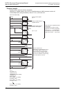
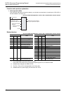
Parameter
*1
1) Auto-tuning: In the case of limit cycle method
The devices are occupied by 29 points from the head device specified by .
2) Auto-tuning: In the case of step response method
a) Action setting (ACT) setting: When all of bit1, bit2, bit5 are other than "0"
The devices are occupied by 25 points from the head device specified by .
b) Action setting (ACT) setting: When all of bit1, bit2, bit5 are "0"
The devices are occupied by 20 points from the head device specified by .
29 points
25 points
20 points
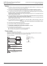
Output value(MV)
1) In the case of PID control (in ordinary processing)
The initial output value is set at the user side before instruction drive.
Thereafter, operation results are stored.
2) Auto-tuning: In the case of limit cycle method
ULV value or LLV value is automatically issued during auto-tuning, and specified MV
value is set after auto-tuning.
3) Auto-tuning: In the case of step response method
Please set the step output value at the user side before instruction drive.
During auto-tuning, the MV output cannot be changed at the PID instruction side.
1 point
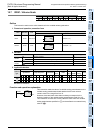
Setting items Content of setting Remarks
Sampling time(TS) 1 to 32767 [ms]
Value shorter than operation cycle cannot be
executed.
+1
Action setting
(ACT)
bit0 0: Normal action 1:Reverse action Direction of action
bit1
0: Input change amount alarm absent
1: Input change amount alarm valid
bit2
0: Output change amount alarm absent
1: Output change amount alarm valid
Do not turn ON bit2 and bit5 simultaneously.
bit3 Not usable.
bit4
*2
0: Auto-tuning inaction
1: Auto-tuning execute
bit5
*2
0: Output value upper and lower limit
setting absent
1: Output value upper and lower limit
setting valid
Do not turn ON bit2 and bit5 simultaneously.
bit6
*2,*3
0: Step response method
1: Limit cycle method
Selection of auto-tuning mode
bit7 to bit15 Not usable.
+2
Input filter constant (α) 0 to 99 [%] No input filter in the case of 0
+3
Proportional gain (KP) 1 to 32767 [%]
+4
Integral time(TI) 0 to 32767 [×100ms] Handled as ∞ in the case of 0 (No integral)
+5
Differential gain (KD) 0 to 100 [%] No differential gain in the case of 0
+6
Differential time(TD) 0 to 32767 [×10ms] No differentiation in the case of 0
+7
:
+19
Occupied by the internal processing of PID operation. Do not change the data.
+20
*1
Input change amount (increase
side) alarm setting value
0 to 32767
Direction of action(ACT): valid if + 1 bit1 is 1
+21
*1
Input change amount (decrease
side) alarm setting value
0 to 32767
Direction of action(ACT): valid if + 1 bit1 is 1