


12 Applied Instructions (High Speed Processing)
266
FXCPU Structured Programming Manual
[Basic & Applied Instruction]
12.3 MTR / Input Matrix
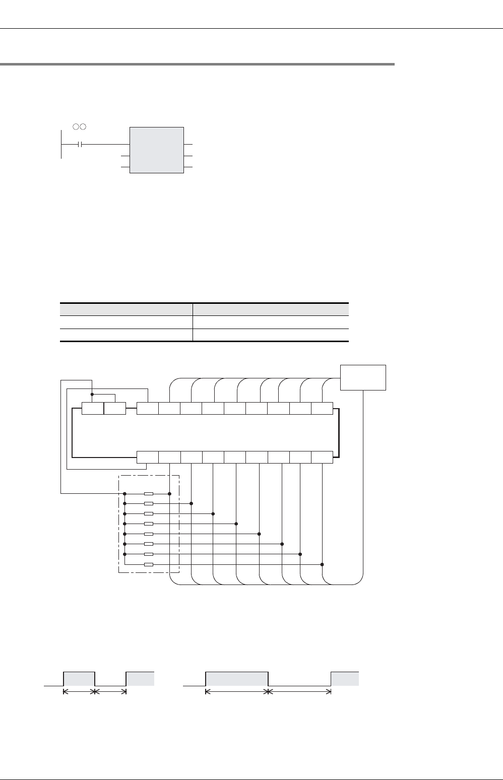
12.3.1 Operation and cautions for MTR instruction
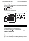
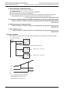
1. Command input
1) Setting the command input to normally ON
For the MTR instruction, set the command input to normally ON.
2. Input numbers used in MTR instruction
1) Inputs available in MTR instruction
Use inputs X020 and later under normal conditions.
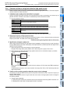
2) When using the inputs X000 to X017 (X000 to X007 for 16-point type main unit)
The receiving speed is higher. Because the output transistor recovery time is long and the input
sensitivity is high, however, erroneous input pulses may be counted.
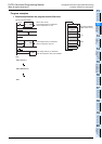
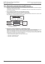
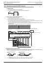
To prevent erroneous input pulses, connect pull-up resistors (3.3 kΩ / 0.5W) to transistor outputs used in
MTR instruction.
For pull-up resistors, use the power supply shown in the table below.
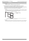
The figure below shows an example of the FX
3U series main unit (sink input / sink output).
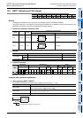
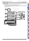
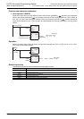
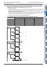
3. ON/OFF duration of input signals
Because 64 input points (8 rows × 8 columns) are received in a cycle of 80 or 160 ms, the ON/OFF duration
of each input signal should be greater than or equal to the value shown below.
*1. X000 to X007 for FX
U, FX2C, FX1S, FX1N, FX1NC, FX3G and FX3GC PLCs.
*2. X010 and later for FX
U, FX2C, FX1S, FX1N, FX1NC, FX3G, FX3GC PLCs.
Power supply used for pull-up resistors
AC power type PLC Service power supply
DC power type PLC Power supply for driving PLC
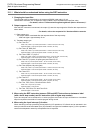
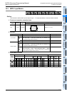
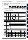
MTR
EN
s
n
ENO
d1
d2
X020
K 8
Y040
M 0
M
(Normally ON)
COM5 Y020 Y021 Y022 Y023 Y024 Y025 Y026 Y027
0V
X000 X001 X002 X003 X004 X005 X006 X007
Matrix
circuit
3.3kΩ/0.5W
FX3U-64MT/ES
Transistor output
Pull-up resistor
Refer to the previous page.
24V S/S
80ms
When inputs X000 to X017
*1
are used
When inputs X020
*2
and later are used
80ms
160ms 160ms