


20 Applied Instructions (Positioning Control)
20.5 ZRN / Zero Return
529
FXCPU Structured Programming Manual
[Basic & Applied Instruction]
11
Applied Instructions
(Data Operation)
12
Applied Instructions
(High Speed
Processing)
13
Applied Instructions
(Handy
Instruction)
14
Applied Instructions
(External FX I/O
Device)
15
Applied Instructions
(External Device
(optional device))
16
Applied Instructions
(External Device)
17
Applied Instructions
(Data Transfer 2)
18
Applied Instructions
(Floating Point)
19
Applied Instructions
(Data Operation 2)
20
Applied Instructions
(Positioning
Control)
Cautions
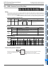
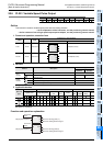
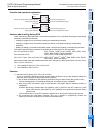
1) Instruction driving timing (FX1S, FX1N, FX1NC PLCs)
This is an instruction allowed to program as many times as desired, but you are advised to design the
instruction driving timing according to the following cautions.
a) Do not drive simultaneously the positioning instruction using the same output relay (Y000 or Y001).
If driven simultaneously, it is handled as double coil, and normal function is disabled.
b) After turning OFF the direction input of the instruction, drive again after the following condition is
established.
Condition:Re-driving is allowed after one operation cycle or more from the OFF moment of "pulse
output mode monitor (Y000: [M8147], Y001: [M8148]" of the positioning instruction driven
previous time.
This is because one or more OFF operation is required for re-driving of the positioning instruction.
c) We recommend the step-ladder instruction (STL) as a method of programming correctly the
positioning instruction according to the cautions mentioned above.
2) Not applicable to DOG search function, please start the zero return operation from the front side of the
near-point signal. (FX
1S, FX1N, FX1NC PLCs.)
3) Not applicable to zero-point signal of servo motor, please adjust to the position of near-point signal (DOG)
when fine adjustment of zero point is necessary. (FX
1S, FX1N, FX1NC PLCs.)
4) While zero return, the numeric values of the current value registers (Y000: [D8141, D8140], Y001:
[D8143, D8142]) move in the decreasing direction. (FX
1S, FX1N, FX1NC PLCs)
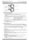
When zero return in reverse direction, please control the output relay (Y) wired as "rotating direction
signal" by the program in the following procedure.
1) Set (ON) Y
(rotating direction signal).
2) Execute zero return instruction.
3) Reset (OFF) Y
(rotating direction signal) by execution complete flag (M8012) of zero return
instruction.
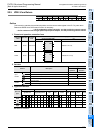
5) Some restrictions to applicable devices.
S1: The FX
3U and FX3UC PLCs only are applicable, index (V, Z) decoration is disabled.
S2: The FX
3U and FX3UC PLCs only are applicable.
S3: The FX
3G, FX3GC, FX3U and FX3UC PLCs only are applicable.
S4: <FX
3S, FX3G, FX3GC, FX3U, FX3UC PLCs>
Please specify Y000, Y001, Y002
*1
of transistor output of basic unit, or Y000, Y001, Y002
*3
, Y003
*3
of high speed output special adapter
*2
.
*1 The pulse output destination Y002 is not available in FX
3S, FX3G (14-point and 24-point type)
and FX
3GC PLCs.
*2 High speed output special adapter can be connected only in FX
3U PLC.
*3 When using Y002, Y003 in high speed output special adapter, a second high speed output
special adapter is needed.
Points
• When using FX3U PLC of relay output type or triac output type, high speed output special
adapter is needed.
• The output of high speed output special adapter is a differential line driver.
<FX
1S, FX1N, FX1NC PLCs>
Specify Y000 or Y001.
As the output of the PLC, please use the transistor output.