


5 Basic Instruction
52
FXCPU Structured Programming Manual
[Basic & Applied Instruction]
5. Basic Instruction
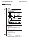
This chapter introduces the instructions for the structured project corresponding to the basic instructions for
the simple project.
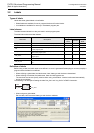
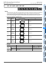
Instruction name Function Reference
LD Initial logical operation of NO (normally open) contacts Section 5.1
LDI Initial logical operation of NC (normally closed) contact type Section 5.1
AND Serial connection of NO (normally open) contacts Section 5.1
ANDI Serial connection of NC (normally closed) contacts Section 5.1
OR Parallel connection of NO (normally open) contacts Section 5.1
ORI Parallel connection of NC (normally closed) contacts Section 5.1
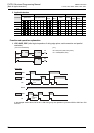
LDP Initial logical operation of rising edge pulse Section 5.2
LDF Initial logical operation of falling/trailing edge pulse Section 5.2
ANDP Serial connection of rising edge pulse Section 5.2
ANDF Serial connection of falling/trailing edge pulse Section 5.2
ORP Parallel connection of rising edge pulse Section 5.2
ORF Parallel connection of falling/trailing edge pulse Section 5.2
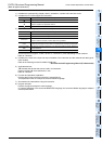
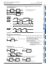
OUT Final logical operation type coil drive (Excluding timers and counters) Section 5.3
OUT_T Final logical operation type coil drive (timers) Section 5.4
OUT_C Final logical operation type coil drive (16-bit counter) Section 5.5
OUT_C_32 Final logical operation type coil drive (32-bit counter) Section 5.5
AND(...) Serial connection of multiple parallel circuits Section 5.6
OR(...) Parallel connection of multiple contact circuits Section 5.6
MPS Stores the current result of the internal PLC operations Section 5.7
MRD Reads the current result of the internal PLC operations Section 5.7
MPP Pops (recalls and removes) the currently stored result Section 5.7
INV Invert the current result of the internal PLC operations Section 5.8
MEP Conversion of operation result to leading edge pulse Section 5.9
MEF Conversion of operation result to trailing edge pulse Section 5.9
SET SET Bit device latch ON Section 5.10
RST RESET Bit device OFF Section 5.10
PLS Rising edge pulse Section 5.11
PLF Falling/trailing edge pulse Section 5.11
MC Denotes the start of a master control block Section 5.12
MCR Denotes the end of a master control block Section 5.12
END Program END, I/O refresh and Return to Step 0 Section 5.13
NOP No operation or null step Section 5.14