


35 Interrupt Function and Pulse Catch Function
812
FXCPU Structured Programming Manual
[Basic & Applied Instruction]
35.7 Pulse Catch Function[M8170 to M8177]
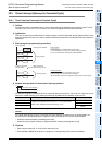
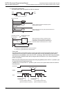
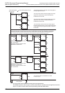
2. Program example
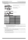
*1. When using the pulse catch function at 5μs or when receiving a pulse whose response frequency is
50 kHz to 100 kHz using a high speed counter, perform the following:
- Make sure that the wiring length is 5 m or less.
- Connect a bleeder resistor of 1.5 Ω (1 W or more) to an input terminal, and make sure that the load
current of the open collector transistor output in the counterpart equipment is 20 mA or more
including the input current in the main unit.
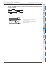
3. Cautions on use
1) When receiving an input again, it is necessary to reset the device which was once set using a program.
Accordingly, until a device is reset, a new input cannot be received.
2) When it is necessary to receive continuous short pulses (input signals), use the external input interrupt
function or high speed counter function.
3) A filter adjustment program is not required.
4) The pulse catch function is executed regardless of the operations of the special auxiliary relays M8050 to
M8055 for respectively disabling interrupts.
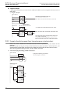
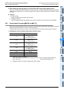
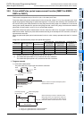
PLC Input number Pulse width
FX3U, FX3UC
X000 to X005
5 μs or more
*1
X006, X007 50 μs or more
FX3G, FX3GC
X000, X001, X003, X004 10 μs or more
X002, X005 50 μs or more
FX3S
X000, X001 10 μs or more
X002 to X005 50 μs or more
FX2N, FX2NC
X000, X001 20 μs or more
X002, X005 50 μs or more
FX1S, FX1N, FX1NC
X000, X001 10 μs or more
X002, X005 50 μs or more
FX2, FX2C X000 to X005 50 μs or more
FX0S, FX0, FX0N X000 to X003 50 μs or more
The FX
0S
, FX
0
, FX
0N
, FX
1S
, FX
1N
, FX
1NC
, FX
3S
, FX
3G
or FX
3GC
PLC
does not require the EI instruction.
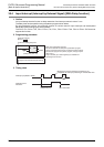
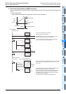
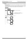
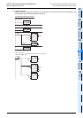
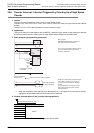
When the rising edge of X000 is detected,
M8170 is set as interrupt.
The pulse catch result is reset.
Reset
input
Input pulse width (shown below)
EI
X000 (Input)
M8170
X002 (Reset)