6 Step Ladder Instructions
6.1 Step Ladder
99
FXCPU Structured Programming Manual
[Basic & Applied Instruction]
1
Outline
2
Instruction List
3
Configuration of
Instruction
4
How to Read
Explanation of
Instructions
5
Basic Instruction
6
Step Ladder
Instructions
7
Applied Instructions
(Program Flow)
8
Applied Instructions
(Move and
Compare)
9
Applied Instructions
(Arithmetic and
Logical Operation)
10
Applied Instructions
(Rotation and
Shift Operation)
6.1.3 Program examples
Examples of single flows
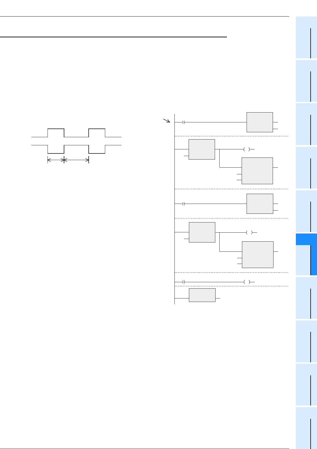
1. Example of flicker circuit
• When the PLC mode is changed from STOP to RUN, the state relay S3 is driven by the initial pulse
(M8002).
• The state relay S3 outputs Y000. One second later, the ON status transfers to the state relay S20.
• The state relay S20 outputs Y001. 1.5 seconds later, the ON status returns to the state relay S3.
1 second 1.5 second
Y000
Y001
[Structured ladder/FBD]
[ ST ]
SET(M8002,S3);
STL(TRUE, S3);
Y000:=TRUE;
OUT_T(TRUE, TC0,K10);
SET(TS0, S20);
STL(TRUE, S20);
Y001:=TRUE;
OUT_T(TRUE, TC1, K15);
S3:=TS1;
RET(TRUE);
M8002
Initial
pulse
Y000
S3
STL
EN ENO
s
SET
EN ENO
d S3
Y001
S20
STL
EN ENO
s
S3
OUT_T
EN ENO
TC0
TCoil
TValue
K10
TS0
SET
EN ENO
d S20
OUT_T
EN ENO
TC1
TCoil
TValue
K15
TS1
RET
EN ENO
Step
number
0
3
8
11
16
19


