


12 Applied Instructions (High Speed Processing)
301
FXCPU Structured Programming Manual
[Basic & Applied Instruction]
11
Applied Instructions
(Data Operation)
12
Applied Instructions
(High Speed
Processing)
13
Applied Instructions
(Handy
Instruction)
14
Applied Instructions
(External FX I/O
Device)
15
Applied Instructions
(External Device
(optional device))
16
Applied Instructions
(External Device)
17
Applied Instructions
(Data Transfer 2)
18
Applied Instructions
(Floating Point)
19
Applied Instructions
(Data Operation 2)
20
Applied Instructions
(Positioning
Control)
12.8 PLSY / Pulse Y Output
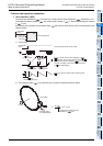
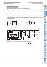
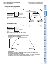
7. Cautions on using special high speed output adapters (FX3U PLC)
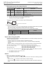
1) Outputs of special high speed output adapters work as differential line drivers.
2) Set the pulse output type setting switch in a special high speed output adapter to the "pulse train +
direction" (PLS - DIR) side.
If the switch is set to the "forward rotation pulse train - reverse rotation pulse train" (FP - RP) side, normal
operation is disabled. The pulse output destination changes depending on the PLC output status as
shown in the table below.
3) Set the pulse output type setting switch while the PLC is in STOP or while the power is OFF.
Do not manipulate the pulse output type setting switch while pulses are being output.
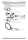
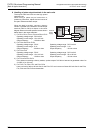
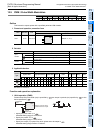
4) When special high speed output adapters are connected, the same output numbers in the main unit are
assigned as shown in the table below.
Only wire the appropriate terminals. (Use either one only. Do not connect to the other terminal.)
Outputs of special high speed output adapters and main units operate as follows.
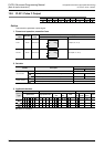
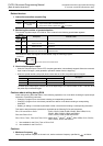
Assignment of output numbers in special high speed output adapters
Output operation
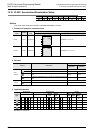
8. Others
1) When using the same output relay (Y000 or Y001) in several instructions.
While a pulse output monitor (BUSY/READY) flag is ON a pulse output instruction and positioning
instruction for the same output relay cannot be executed.
While a pulse output monitor flag is ON even after the instruction drive contact is set to OFF, a pulse
output instruction or positioning instruction for the same output relay cannot be executed.
Before executing such an instruction, wait until the pulse output monitor flag turns OFF and one or more
operation cycles pass.
(Only the FX
1S, FX1N, FX1NC, FX3S, FX3G, FX3GC, FX3U and FX3UC PLCs are compatible with the pulse
output monitor flags.)
2) "Frequency control mode" in which DHSZ and DPLSY instructions are combined can be used only once
in a program.
Pulse output
destination
Output affecting
operation
Operation
= Y000
Y004
While Y004 is ON, pulses are output from Y000 in the high speed output adapter.
While Y004 is OFF, pulses are output from Y004 in the high speed output adapter.
= Y001
Y005
While Y005 is ON, pulses are output from Y001 in the high speed output adapter.
While Y005 is OFF, pulses are output from Y005 in the high speed output adapter.
Status of output type
setting switch
Signal name
Setting name in
each positioning
instruction
Output number
1st unit 2nd unit
1st axis 2nd axis 3rd axis 4th axis
"FP - RP" side
Forward rotation pulse
train (FP)
Pulse output destina-
tion
Y000 Y001 Y002 Y003
Reverse rotation pulse
train (RP)
Rotation direction
signal
Y004 Y005 Y006 Y007
"PLS - DIR" side
Pulse train
Pulse output destina-
tion
Y000 Y001 Y002 Y003
Direction
Rotation direction
signal
Y004 Y005 Y006 Y007
Output operation
Relay output type or triac output type main unit
While instruction is activated, relevant output is ON. (LED is also ON.)
Use special high speed output adapter.
Special high speed output adapter
Operated (LED operated.)
Set the output frequency to "200 kHz" or less.
Transistor output type main unit
Operated (LED is also ON.)
Set the output frequency to "100 kHz" or less.
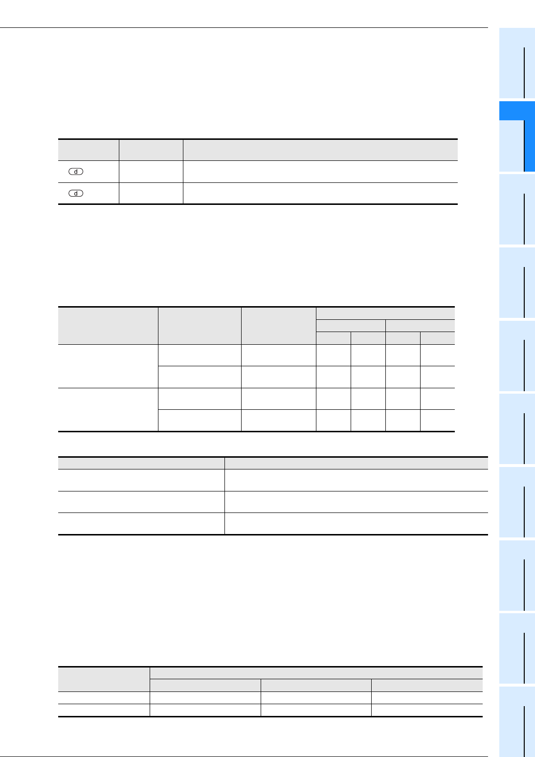
Pulse output destination
device
Pulse output monitor flag
FX3U, FX3UC FX3S, FX3G, FX3GC FX1N, FX1NC, FX1S
Y000 M8340 M8340, M8147 M8147
Y001 M8350 M8350, M8148 M8148