


14 Applied Instructions (External FX I/O Device)
14.6 ARWS / Arrow Switch
374
FXCPU Structured Programming Manual
[Basic & Applied Instruction]
Cautions
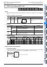
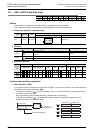
1. Setting of parameter n
Refer to the parameter setting of SEGL instruction. However, the setting range is 0 to 3.
2. Output format of PLC
Use the PLC of transistor output type.
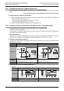
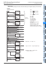
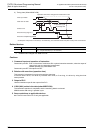
3. Scan time (operation period) and display timing
ARWS instruction is executed in synchronism with the scan time (operation cycle) of the PLC.
To execute a series of displays, 10 ms or more is needed in the scan time of the PLC. If less than 10 ms, you
must use the constant scan mode and operate in scan time of 10 ms or more.
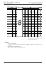
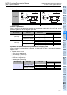
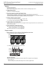
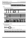
4. Number of bits occupied in device
1) The input of the device specified by occupies 4 bits.
2) The output of the device specified by occupies 8 bits.
5. Limit of times of use of instruction
ARWS instruction can be used only once in the program. When using this instruction two or more times, use
index function to program.
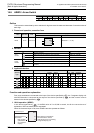
6. Some restrictions to applicable devices.
S1: The FX3U and FX3UC PLCs only are applicable.
However, index modifier (V, Z) is not applicable.
S2: The FX
3U and FX3UC PLCs only are applicable.
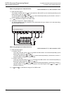
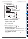
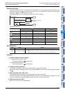
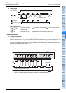
Program example
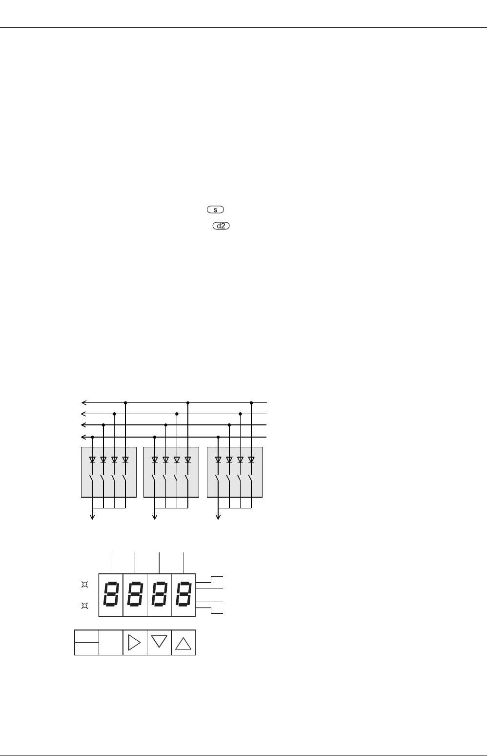
1. When changing the timer setting and displaying the current value
1) Specify the timer number by 3-digit digital switch
2) Setting of constant value of timer by arrow switch
Operation explanation
Every time read/write key is pressed, the read and write LED is changed over and displayed.
• When reading out
Press the setting switch (X003) after setting the timer number by digital switch.
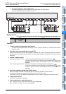
X013
X010
X011
X012
10
1
184
Y011
2
10
0
184
Y010
2
10
2
184
Y012
2
Y004
Y015
Y007
Y006
Y005
Read out
Write in
Y003
Read out
8
Y000
Y001
Y002
Y014
1
2
4
X001
Setting
Write in
X004 X003 X002 X000