


14 Applied Instructions (External FX I/O Device)
14.5 SEGL / Seven Segment With Latch
368
FXCPU Structured Programming Manual
[Basic & Applied Instruction]
When using 4 digits and 1 set(n=K0 to K3)
→ As for selection of "n", refer to section 14.5.2.
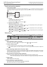
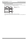
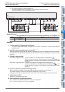
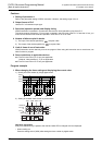
1) Data and strobe signal
The 4-digit numerical value of is converted from BIN to BCD, and is issued sequentially by time
division digit by digit from to +3.
The strobe signal output ( +4 to +7) is also issued sequentially by time division, and the 7-
segment display of 4 digits and 1 set is latched.
2) In , BIN data in a range of 0 to 9,999 is valid.
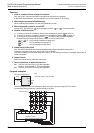
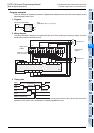
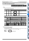
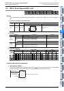
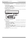
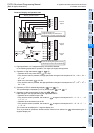
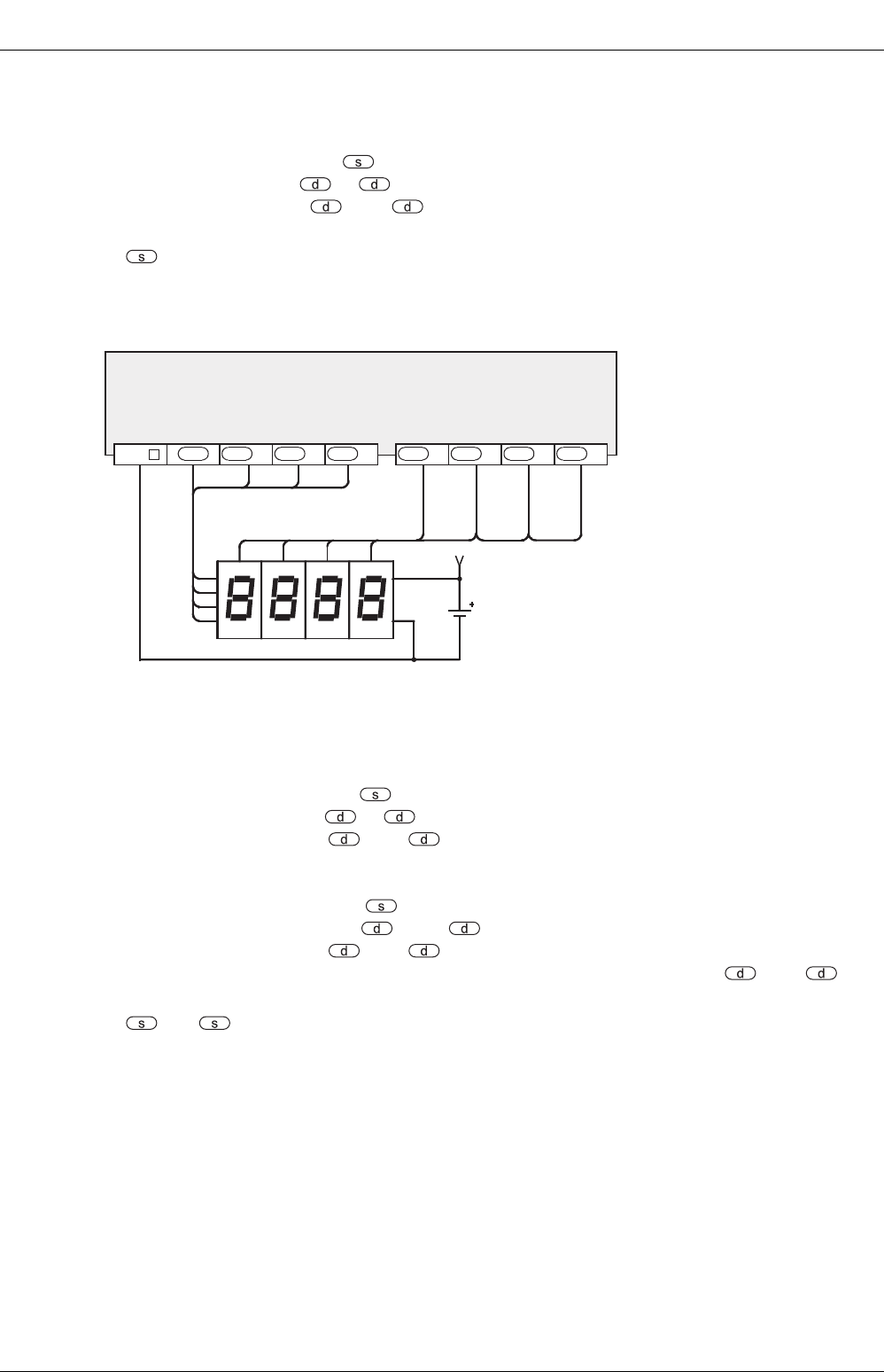
3) Connection example of 7-segment display unit
The following diagram show an example of FX
3U series basic unit (sync output). As for the actual wiring,
see the manual of the PLC.
When using 4 digits and 2 sets(n=K4 to K7)
→ As for selection of "n", refer to section 14.5.2.
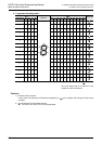
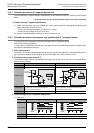
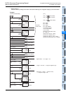
1) Data and strobe signal
a) 4 digits, first set
The 4-digit numerical value of is converted from BIN to BCD, and is issued sequentially by time
division digit by digit from to +3.
The strobe signal output ( +4 to +7} is also issued sequentially by time division, and the 7-
segment display of 4 digits and 1 set is latched.
b) 4 digits, second set
The 4-digit numerical value of +1 is converted from BIN to BCD, and is issued sequentially by
time division digit by digit from +10 to +13.
The strobe signal output ( +4 to +7) is also issued sequentially by time division, and the 7-
segment display of 4 digits and 2 sets is latched. (The strobe signal output ( +4 to +7) is
common in each set.)
2) In and +1, BIN data in a range of 0 to 9,999 is valid.
10
0
4
2
81
1
2
4
8
First set
V+
10
1
10
2
10
3
10
3
10
2
10
1
10
0
+3
PLC (transistor output)
d
+2
d
+1
dd
COM
+6
d
+5
d
+4
d
+7
d