


12 Applied Instructions (High Speed Processing)
303
FXCPU Structured Programming Manual
[Basic & Applied Instruction]
11
Applied Instructions
(Data Operation)
12
Applied Instructions
(High Speed
Processing)
13
Applied Instructions
(Handy
Instruction)
14
Applied Instructions
(External FX I/O
Device)
15
Applied Instructions
(External Device
(optional device))
16
Applied Instructions
(External Device)
17
Applied Instructions
(Data Transfer 2)
18
Applied Instructions
(Floating Point)
19
Applied Instructions
(Data Operation 2)
20
Applied Instructions
(Positioning
Control)
12.9 PWM / Pulse Width Modulation
12.9 PWM / Pulse Width Modulation
Outline
This instruction outputs pulses with a specified period and ON duration.
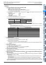
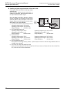
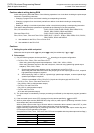
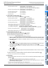
1. Format and operation, execution form
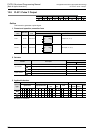
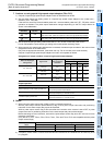
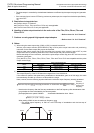
2. Set data
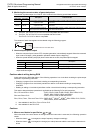
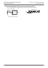
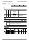
3. Applicable devices
S: Refer to "Cautions".
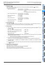
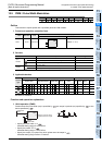
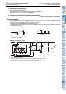
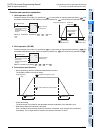
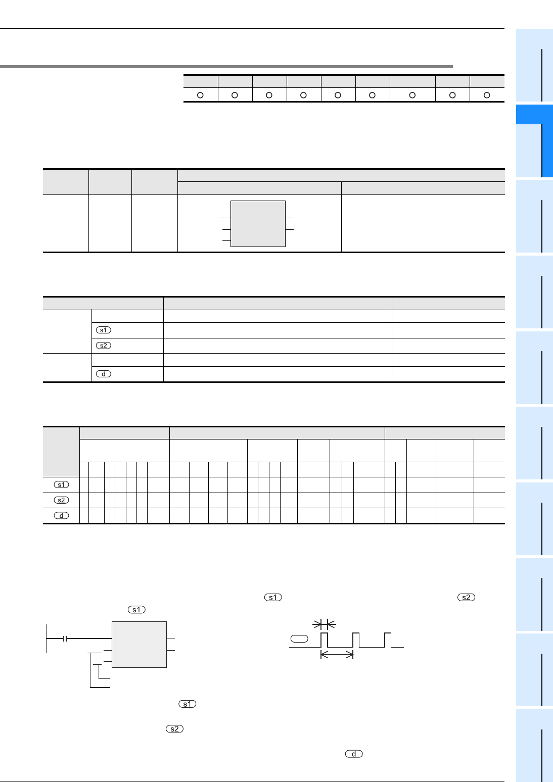
Function and operation explanation
1. 16-bit operation (PWM)
Pulses whose ON pulse width (ms) is specified by are output in periods (ms) specified by to the
device specified by
• Specify the pulse width "t" in .
Allowable setting range: 0 to 32,767ms
• Specify the period "T0" in
Allowable setting range: 1 to 32,767ms
• Specify the output (Y) number from which pulses are to be output in .
Allowable setting range: Refer to "Cautions".
FX3U(C) FX3G(C) FX3S FX2N(C) FX1N(C) FX1S FXU/FX2C FX0N FX0(S)
Instruction
name
Operation
Execution
form
Expression in each language
Structured ladder/FBD ST
PWM 16 bits Continuous PWM(EN, s1, s2, d);
Variable Description Data type
Input
variable
EN Execution condition Bit
Pulse width (ms) data or word device storing the data ANY16
Period data (ms) or word device storing the data ANY16
Output
variable
ENO Execution state Bit
Device (Y) from which pulses are to be output Bit
Operand
type
Bit Devices Word Devices Others
System User Digit Specification System User
Special
Unit
Index
Cons
tant
Real
Number
Character
String
Pointer
XYMTCS
D
.b
KnX KnY KnM KnS
TCD R
U
\G
VZ
Modifier
KH E
"
"
P
zzzzzzz
S2 S3
zz z zz
zzzzzzz
S2 S3
zz z zz
S1
z
PWM
EN
s1
s2
ENO
d
Command
input
t
T
0
Pulse width
Period
PWM
EN
s1
s2
ENO
d
t
T
0
d
Device (Y) from which
pulses are to be output