


30 Applied Instructions (External Device Communication)
30.7 ADPRW / MODBUS Read/Write
725
FXCPU Structured Programming Manual
[Basic & Applied Instruction]
21
Applied Instructions
(Real Time
Clock Control)
22
Applied Instructions
(External Device)
23
Applied Instructions
(Extension
Function)
24
Applied Instructions
(Others)
25
Applied Instructions
(Block Data
Operation)
26
Applied Instructions
(Character
String Control)
27
Applied Instructions
(Data Operation 3)
28
Applied Instructions
(Data Comparison)
29
Applied Instructions
(Data Table
Operation)
30
Applied Instructions
(External Device
Communication)
Cautions
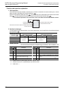
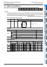
1) The instruction is provided in the FX3U and FX3UC PLCs Ver. 2.40 or later.
The instruction is provided in the FX
3G PLC Ver. 1.30 or later.
2) It is not permitted to use an "ADPRW" instruction and a following instruction for the same port:
- "RS or RS2" instruction
- "IVCK, IVDR, IVRD, IVWR, IVBWR
*1
, IVMC" instruction
-"FLCRT
*1
, FLDEL
*1
, FLWR
*1
, FLRD
*1
, FLCMD
*1
or FLSTRD
*1
" instruction
3) Some restrictions to applicable devices
S1: Excluding special auxiliary relays (M) and Special data register (D).
S2: The FX
3U and FX3UC PLCs only are applicable.
*1. The instruction is not provided in the FX
3S, FX3G and FX3GC PLCs.
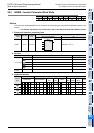
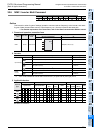
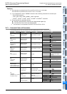
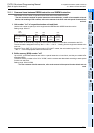
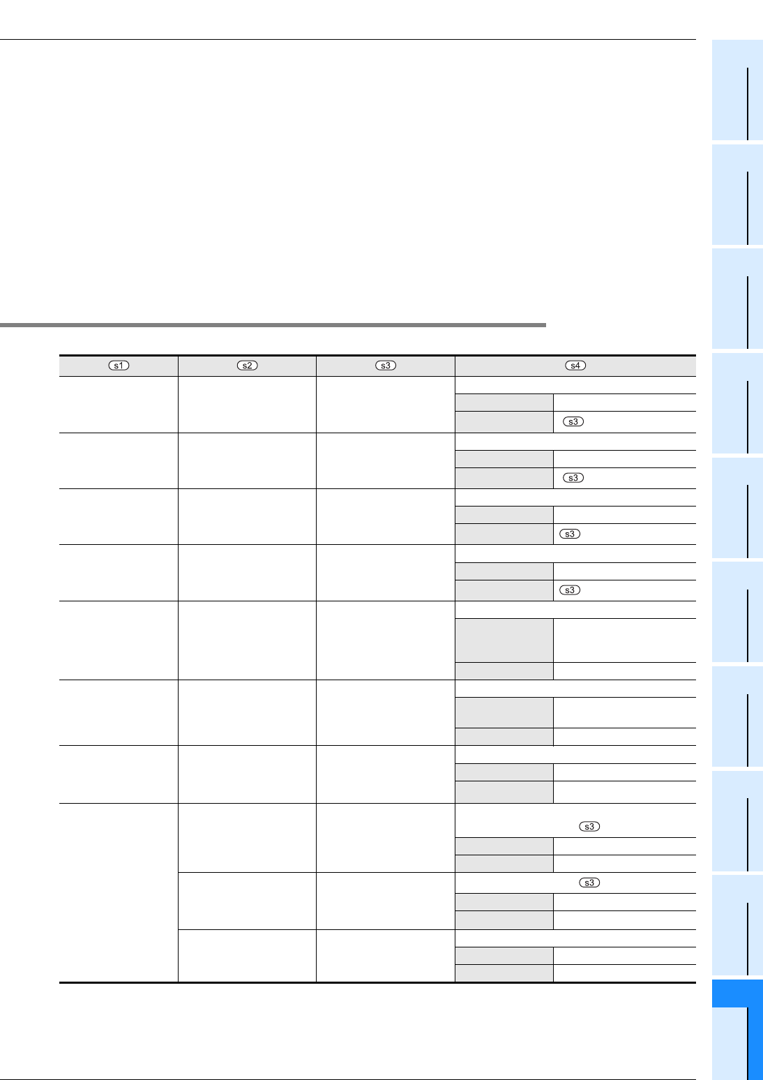
30.7.1 Command Code and Parameters
The following table shows the required command parameters for each command code.
1H
Read Coils
MODBUS Address:
0000H to FFFFH
Device Count: 1 to 2000
PLC Destination Device (head address)
Applicable Devices D, R, M, Y, S
Block Length
(+15) ÷16
*2
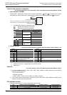
2H
Read Discrete
Inputs
MODBUS Address:
0000H to FFFFH
Device Count: 1 to 2000
PLC Destination Device (head address)
Applicable Devices D, R, M, Y, S
Block Length
(+15) ÷16
*2
3H
Read Holding
Register
MODBUS Address:
0000H to FFFFH
Device Count: 1 to 125
PLC Destination Device (head address)
Applicable Devices D, R
Block Length
4H
Read Input
Register
MODBUS Address:
0000H to FFFFH
Device Count: 1 to 125
PLC Destination Device (head address)
Applicable Devices D, R
Block Length
5H
Write Single Coil
MODBUS Address:
0000H to FFFFH
0 (fixed)
PLC Sourse Device (head address)
Applicable Devices
D, R, K, H, X, Y, M, S
(D, R, X, Y, M, S can be
indexed.)
Block Length 1 Point
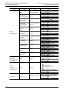
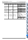
6H
Write Single
Register
MODBUS Address:
0000H to FFFFH
0 (fixed)
PLC Source Device (head address)
Applicable Devices
D, R, K, H
(D, R can be indexed.)
Block Length 1 Point
7H
Read Exception
State (Available only in
FX
3U
and FX
3UC
PLCs)
0 (fixed) 0 (fixed)
PLC Destination Device (head address)
Applicable Devices D, R
Block Length 1 Point
8H
Diagnosis
(Available only in FX3U
and FX3UC PLCs)
Sub-function: 0H
Loop-back Test
Sub-function Data
(loop-back data): 0 to 65535
Loop-back Test Data
(Slave response: echo of )
Applicable Devices D, R
Block Length 1 Point
Sub-function: 1H
Restart
Communication
Sub-function Data:
0x0000: Do Not Reset
Event Log
0xFF00: Reset Event Log
(Slave response: echo of )
Applicable Devices D, R
Block Length 1 Point
Sub-function: 2H
Return
Diagnostic Register
0 (fixed)
PLC Destination Device (head address)
Applicable Devices D, R
Block Length 1 Point
*2. This calculation formula is applicable when the applicable device is D or R.