


11 Applied Instructions (Data Operation)
11.1 ZRST / Zone Reset
228
FXCPU Structured Programming Manual
[Basic & Applied Instruction]
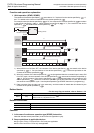
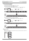
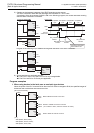
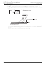
5) Caution on simultaneous instances of the ZRST instruction and a counter
The ZRST instruction resets also the last stage and reset state of T and C coils.
Accordingly, if the drive contact of X000 is ON in the following program, the counter executes counting
after the ZRST instruction is executed.
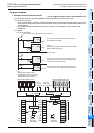
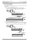
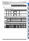
Program in the following way to disable counting after execution of the ZRST instruction.
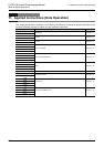
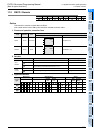
6) Some restrictions to applicable devices
S1:The FX3G, FX3GC, FX3U and FX3UC PLCs only are applicable.
S2:The FX
3U and FX3UC PLCs only are applicable.
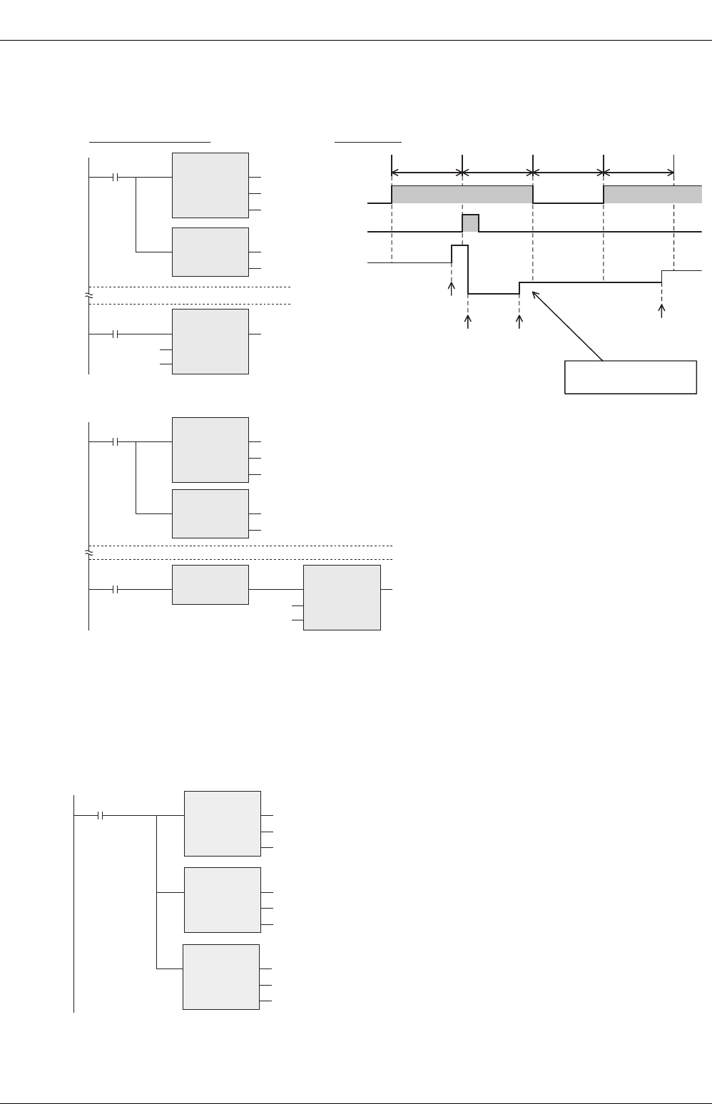
Program examples
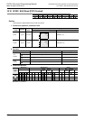
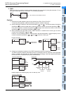
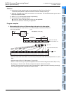
1. When using devices in the latch area as non-latch type devices
When the power of the PLC is turned ON or when the PLC mode is changed to RUN, the specified ranges of
bit devices and word devices are reset at one time.
Timing chart
Structured ladder/FBD
X000
M0
Current
value of C0
3
4
0
1
2
one operation
cycle
OUT_C instruction
execution
ZRST instruction
execution
one operation
cycle
one operation
cycle
one operation
cycle
M0
X000
C0
CC0
K10
M0
C100
ZRST
EN ENO
d1
d2
RST
EN ENO
d
OUT_C
EN ENO
CCoil
CValue
OUT_C instruction
execution
Counting is executed
when X000 is ON.
OUT_C instruction
execution
M0
X000
C0
M0
C100
ZRST
EN ENO
d1
d2
RST
EN ENO
d
MEP
EN ENO
CC0
K10
OUT_C
EN ENO
CCoil
CValue
M500 to M599 are reset at one time.
CN235 to CN255 are reset at one time.
("0" is written to them, and their contacts are reset.)
S500 to S599 are reset at one time.
M8002
M599
ZRST
EN ENO
d1
d2
M500
CN255
ZRST
EN ENO
d1
d2
CN235
S599
ZRST
EN ENO
d1
d2
S500
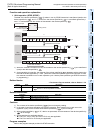
Initial pulse
[Structured ladder/FBD]
[ ST ]
ZRST(M8002, M500, M599);
ZRST(M8002, CN235, CN255);
ZRST(M8002, S500, S599);