


20 Applied Instructions (Positioning Control)
20.5 ZRN / Zero Return
528
FXCPU Structured Programming Manual
[Basic & Applied Instruction]
Function and operation explanation
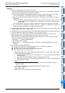
Cautions about writing during RUN
Avoid writing during RUN after either of the following operations in a circuit block including the pulse output
instruction or positioning instruction.
• Changing a program for a circuit block including a corresponding instruction.
• Changing a program for a circuit block just before or after a circuit block including a corresponding
instruction.
• Deleting or adding a circuit block just before or after a circuit block including a corresponding instruction.
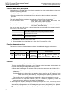
This caution about the above operations is applicable to the following PLCs and instructions.
FX
1S, FX1N and FX1NC PLCs : PLSY, DPLSY, PWM, PLSR, DPLSR, ZRN, DZRN, PLSV,
DPLSV, DRVI, DDRVI, DRVA and DDRVA
FX
2N and FX2NC PLCs : PLSY, DPLSY, PWM, PLSR and DPLSR
FX
3S, FX3G, FX3GC, FX3U and FX3UC PLCs: DSZR, DVIT
*1
, DDVIT
*1
, DTBL
*2
, ZRN, DZRN, PLSV, DPLSV,
DRVI, DDRVI, DRVA and DDRVA
Note that the pulse output will decelerate and stop when writing during RUN is executed in the FX
3S, FX3G,
FX
3GC, FX3U or FX3UC PLC.
*1. Not available for the FX
3S, FX3G or FX3GC PLC.
*2. Not available for the FX
3S PLC.
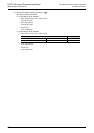
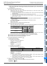
Function changes by version
This instruction includes the function changes as shown in the table below depending on the version.
→ As for the explanation of the instruction and contents of function changes, refer to the positioning
control manual.
1. FX3S PLC, FX3G PLC, FX3GC PLC, FX3U PLC, FX3UC PLC [V2.20 or later]
When the special auxiliary relay corresponding to is turned ON, the output destination of clear signal is
changed to the output number specified by the special data register corresponding to .
2. FX1S PLC
[Before V2.00]
After resetting the "rotating direction signal" (normal rotation output) used in other positioning instruction by
RST, start to zero return.
When started to zero return while the "rotating direction signal" is in normal rotation output state, the motor
moves to the normal rotation, not zero return.
[After V2.00]
When driving of other positioning instruction is turned OFF, the rotating direction signal is turned OFF at the
same time, and processing of before V2.00 is not required.
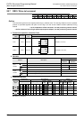
3. FX1S, FX1N PLCs
[Before V2.00]
If the zero return speed does not reach the speed specified by the instruction, change the acceleration or
deceleration speed (D8148) to other value than given below.
(For example, if the current value is 150, change to 149 or 151.)
50, 75, 90, 100, 125, 150, 225, 250, 375, 450, 500, 750, 900, 1120, 1500, 2250, 4499, 4500
[After V2.00]
The above processing is not required.
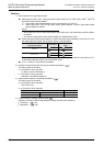
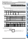
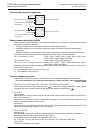
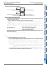
DZRN
EN
s1
ENO
d
Speed when starting to zero return
s2
s3
Command
input
Creep speed
Device for entering the near-point
signal (DOG)
Device for issuing pulse
Speed when starting to zero return
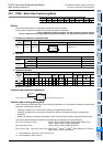
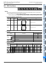
ZRN
EN
s1
ENO
d
s2
s3
Device for entering the near-point
signal (DOG)
Command
input
Creep speed
Device for issuing pulse