


31 Applied Instructions (Data Transfer 3)
31.1 RBFM / Divided BFM Read
730
FXCPU Structured Programming Manual
[Basic & Applied Instruction]
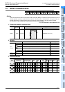
Function and operation explanation
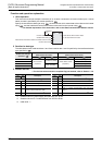
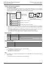
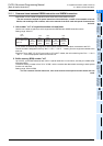
1. 16-bit operation (RBFM)
"n1" buffer memory (BFM) units at location No. "m2" in special function block/unit No. "m1" are transferred
(read) to the device specified by in the PLC. While transferring, "n1" is divided by "n2" so n1/n2 buffer
memories (rounded up when there is a remainder) are transferred per scan time.
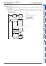
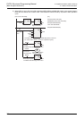
1) When the instruction is finished normally, the instruction execution complete flag M8029 turns ON. When
the instruction is finished abnormally, the instruction execution abnormally complete flag M8329 turns
ON.
2) When RBFM or WBFM instruction in another step is executed for the same unit number, the instruction
non-execution flag M8328 is set to ON, and execution of such an instruction is paused.
When execution of the other target instruction is complete, the paused instruction resumes.
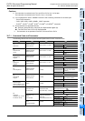
Related devices
Related instructions
Cautions
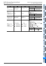
1) The instruction is provided in the FX3UC PLC Ver. 2.20 or later.
2) Some restrictions to applicable devices
S1: Except special data register D
Error
An operation error is caused in the following case. The error flag M8067 turns ON, and the error code is
stored in D8067.
1) When the unit number "m1" does not exist. (Error code: K6708)
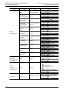
Device Name Description
M8029 Instruction execution complete Turns ON when an instruction is finished normally.
M8328 Instruction non-execution
Turns ON when RBFM or WBFM instruction in another step is executed for the same unit
number.
M8329
Instruction execution abnor-
mally complete
Turns ON when an instruction is finished abnormally.
Instruction Description
FROM Read from a special function block
TO Write to a special function block
WBFM Divided BFM write
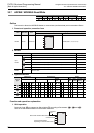
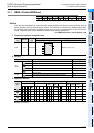
Command input
M8029
M8328
M
M
Instruction execution complete
Instruction non-execution
M8329
M
Instruction execution abnormally complete
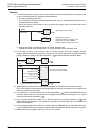
RBFM
EN ENO
m1
m2
n1
n2
d
Unit number
Head BFM number
Number of all
buffer memories
(BFM) to be read
Number of points
transferred in one
operation cycle
Head device storing
data to be read from
buffer memory (BFM)
Read
*1
"n2" buffer memories are read
in each operation cycle.
Reading is executed in "n1/n2" times.
("n1/n2" is rounded up if it is not an integer.)
*1.
PLC
+n1-1
Unit No. "m1"
BFM#(m2)
BFM#(m2+n1-1)
d
d