


13 Applied Instructions (Handy Instruction)
13.6 STMR / Special Timer
338
FXCPU Structured Programming Manual
[Basic & Applied Instruction]
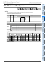
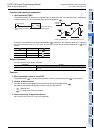
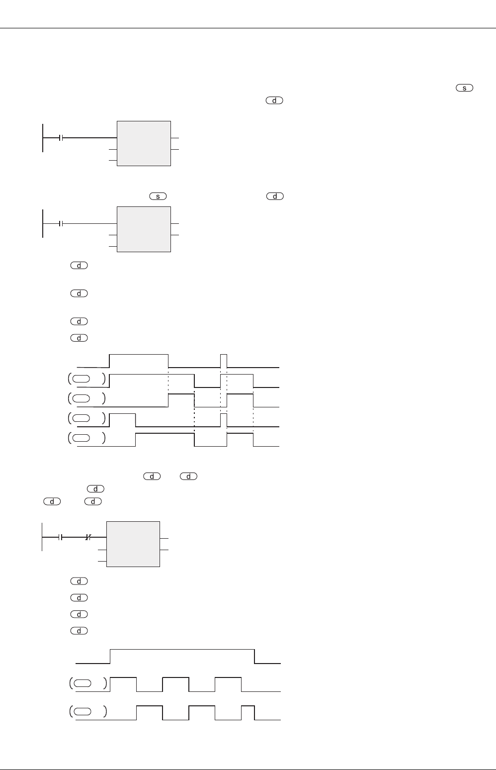
Function and operation explanation
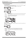
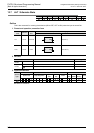
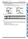
1. 16-bit operation(STMR)
The value designated in m is determined as the set value for the timer of the device designated in , and
is issued to four points from the device designated in .
Create the program depending on the application by referring to the following example.
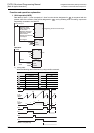
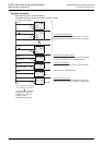
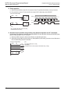
Off-delay timer, one-shot timer
When T10 is assigned in , K100 in m, and M0 in
• M0[ ] : This is an off-delay timer for turning OFF with set time delay of the timer after the command
contact is turned OFF.
• M1[ +1] : This is a one-shot timer for turning OFF after the timer set time by turning ON after the
command contact is changed from ON to OFF.
• M2[ +2] : Occupied. To be used for flicker application.
• M3[ +3] : Occupied.
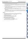
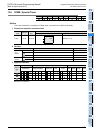
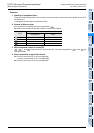
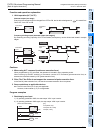
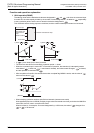
Flicker
The flicker is issued to +1, +2 by preparing the program for turning OFF this command by the b-
contact of +3 as shown below.
and +3 are occupied.
• M0[ ] : Occupied. (To be used in off-delay timer application. See previous page.)
• M1[ +1] : This is the flicker (a-contact) for repeating ON/OFF at timer time intervals.
• M2[ +2] : This is the flicker (b-contact) for repeating ON/OFF at timer time intervals.
• M3[ +3] : Occupied.
Command input
STMR
EN
s
m
ENO
d
Timer to be used
Set value of timer
Beginning bit device
to be output
Command input
STMR
EN
s
m
ENO
d
T10
K100
M0
Command
input
+1
10s
10s
10s10s
10s
+2
+3
M0
M1
M2
M3
d
d
d
d
Command
input
M3
STMR
EN
s
m
ENO
d
T10
K100
M0
Command
input
+1
10s
+2
10s 10s
10s 10s
M1
M2
d
d