


12 Applied Instructions (High Speed Processing)
304
FXCPU Structured Programming Manual
[Basic & Applied Instruction]
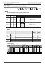
12.9 PWM / Pulse Width Modulation
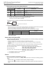
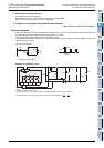
Cautions about writing during RUN
Avoid writing during RUN after either of the following operations in a circuit block including the pulse output
instruction or positioning instruction.
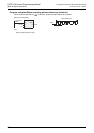
• Changing a program for a circuit block including a corresponding instruction.
• Changing a program for a circuit block just before or after a circuit block including a corresponding
instruction.
• Deleting or adding a circuit block just before or after a circuit block including a corresponding instruction.
This caution about the above operations is applicable to the following PLCs and instructions.
FX
1S, FX1N and FX1NC PLCs : PLSY, DPLSY, PWM, PLSR, DPLSR, ZRN, DZRN, PLSV,
DPLSV, DRVI, DDRVI, DRVA and DDRVA
FX
2N and FX2NC PLCs : PLSY, DPLSY, PWM, PLSR and DPLSR
FX
3S, FX3G, FX3GC, FX3U and FX3UC PLCs: DSZR, DVIT
*1
, DDVIT
*1
, DTBL
*2
, ZRN, DZRN, PLSV, DPLSV,
DRVI, DDRVI, DRVA and DDRVA
*1. Not available for the FX
3S, FX3G or FX3GC PLC.
*2. Not available for the FX
3S PLC.
Cautions
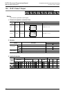
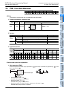
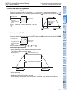
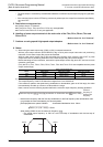
1. Setting the pulse width and period
Make sure that the pulse width and period satisfy the relationship " ≤ ".
2. Pulse output
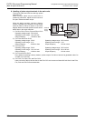
1) Only the following outputs can be specified in according to the system configuration.
•For FX
3S, FX3G, FX3GC, FX3U and FX3UC PLCs
- When using special high speed output adapters
*1
: Y000, Y001, Y002
*2
, Y003
*2
- When using transistor outputs on the main unit (that is, when not using special high speed output
adapters): Y000, Y001, Y002
*3
*1. Special high speed output adapters can be connected only to the FX3U PLC.
When using the PWM instruction with a relay output type or triac output type FX
3U PLC, a special
highspeed output adapter is required.
*2. When specifying Y002 or Y003 on a special high speed output adapter, a second special high
speed output adapter is required.
*3. "Y002 is not available in FX
3S, FX3G PLC (14-point and 24-point type) and FX3GC PLC.
•For FX
1S, FX1N, FX1NC, FX2N and FX2NC PLCs
Only Y000 or Y001 is valid (transistor output).
•For FX
0S, FX0 and FX0N PLCs
Only Y001 is valid (transistor output).
•For FX
U and FX2C PLCs
All Ys are valid (transistor output).
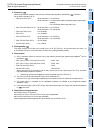
2) The pulse output is controlled by interrupt processing not affected by the sequence program (operation
cycle).
3) If the command input is set to OFF, the output from the device specified by turns OFF.
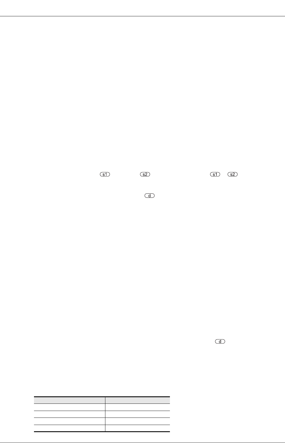
4) While a pulse output monitor (BUSY/READY) flag is ON, a pulse output or positioning instruction for the
same output relay cannot be executed.
While a pulse output monitor flag is ON even after the instruction derive contact is set to OFF, a pulse
output or positioning instruction for the same output relay cannot be executed.
Before executing a pulse output or positioning instruction, wait until the pulse output monitor flag turns
OFF and one or more operation cycles pass.
(Only the FX
3S, FX3G, FX3GC, FX3U and FX3UC PLCs are compatible with the pulse output monitor flags.)
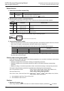
Pulse output destination device Pulse output monitor flag
Y000 M8340
Y001 M8350
Y002 M8360
Y003 M8370