


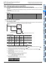
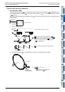
12 Applied Instructions (High Speed Processing)
289
FXCPU Structured Programming Manual
[Basic & Applied Instruction]
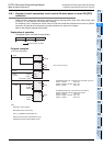
11
Applied Instructions
(Data Operation)
12
Applied Instructions
(High Speed
Processing)
13
Applied Instructions
(Handy
Instruction)
14
Applied Instructions
(External FX I/O
Device)
15
Applied Instructions
(External Device
(optional device))
16
Applied Instructions
(External Device)
17
Applied Instructions
(Data Transfer 2)
18
Applied Instructions
(Floating Point)
19
Applied Instructions
(Data Operation 2)
20
Applied Instructions
(Positioning
Control)
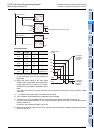
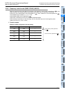
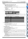
12.6 DHSZ / High Speed Counter Zone Compare
12.6.3 Frequency control mode (DHSZ, DPLSY) (M8132)
When the special auxiliary relay M8132 for declaring the frequency control mode is specified as in the
DHSZ instruction, the special function shown below is provided if DPLSY instruction is combined.
At this time, only a data register D can be specified as , and a constant K or H can be specified as .
The available range is limited to "1 ≤ K, H ≤ 128".
A high speed counter can be specified as .
This function is different from the zone comparison described above.
PLSY instruction is as shown on the next page, and only the pulse output can be changed by users.
(Valid for the FX
U PLC, V3.07 or later)
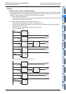
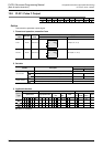
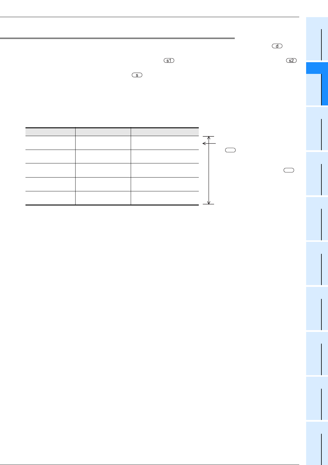
1. Control example
Example of table configuration and data setting
Comparison data Frequency Table counter (D8131)
D 301, D 300
K 20
D 302, D 303
K300
0
↓
D 305, D 304
K600
D 306, D 307
K500
1
↓
D 309, D 308
K700
D 310, D 311
K200
2
↓
D 313, D 312
K800
D 314, D 315
K100
3
↓
D 317, D 316
K 0
D 318, D 319
K 0
4
↓
Head device (32 bits) specified
as
s1
Number of lines specified as
s2