


20 Applied Instructions (Positioning Control)
20.7 DRVI / Drive to Increment
536
FXCPU Structured Programming Manual
[Basic & Applied Instruction]
2) Some restrictions to applicable devices.
S1: <FX
3S, FX3G, FX3GC, FX3U, FX3UC PLCs>
Please specify Y000, Y001, Y002
*1
of transistor output of basic unit, or Y000, Y001, Y002
*3
, Y003
*3
of high speed output special adapter
*2
.
*1. The pulse output destination Y002 is not available in FX
3S, FX3G (14-point and 24-point type)
and FX
3GC PLCs.
*2. High speed output special adapter can be connected only in FX
3U PLC.
*3. When using Y002, Y003 in high speed output special adapter, a second high speed output
special adapter is needed.
Points
• When using FX3U PLC of relay output type or triac output type, high speed output special
adapter is needed.
• The output of high speed output special adapter is a differential line driver.
<FX
1S, FX1N, FX1NC PLCs>
Specify Y000 or Y001.
As the output of the PLC, please use the transistor output.
S2: <FX
3S, FX3G, FX3GC, FX3U, FX3UC PLCs>
When high speed output special adapter is used at the pulse output destination in the FX
3U PLC,
as the rotating direction signal, use the output shown in the table below.
When built-in transistor output is used at the pulse output destination in the FX
3S, FX3G, FX3GC,
FX
3U and FX3UC PLCs, as the rotating direction signal, use the transistor output.
S3: The FX
3U and FX3UC PLCs only are applicable, index (V, Z) decoration is disabled.
S4: The FX
3G, FX3GC, FX3U and FX3UC PLCs only are applicable.
S5: The FX
3U and FX3UC PLCs only are applicable.
3) Number of output pulses is specified by .
The setting range is as follows.
a) In the case of 16-bit operation
-32,768 to +32,767 (excluding 0)
b) In the case of 32-bit operation
-999,999 to +999,999 (excluding 0)
4) The output pulse frequency is specified by .
The setting range is as follows.
a) In the case of 16-bit operation
• In the case of FX
3S, FX3G, FX3GC, FX3U and FX3UC PLCs
10 to 32,767 (Hz)
• In the case of FX
1S and FX1N PLCs
10 to 32,767 (Hz)
• In the case of FX
1NC PLC
10 to 10,000 (Hz)
b) In the case of 32-bit operation
• In the case of FX
3S, FX3G, FX3GC, FX3U and FX3UC PLCs
• In the case of FX
1S and FX1N PLCs
10 to 100,000 (Hz)
• In the case of FX
1NC PLC
10 to 10,000 (Hz)
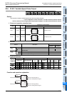
5) Output number of rotating direction signal
Operation changes as follows depending on polarity of output pulse frequency.
[+ (Positive)] → : ON
[- (Negative)] → : OFF
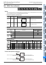
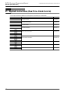
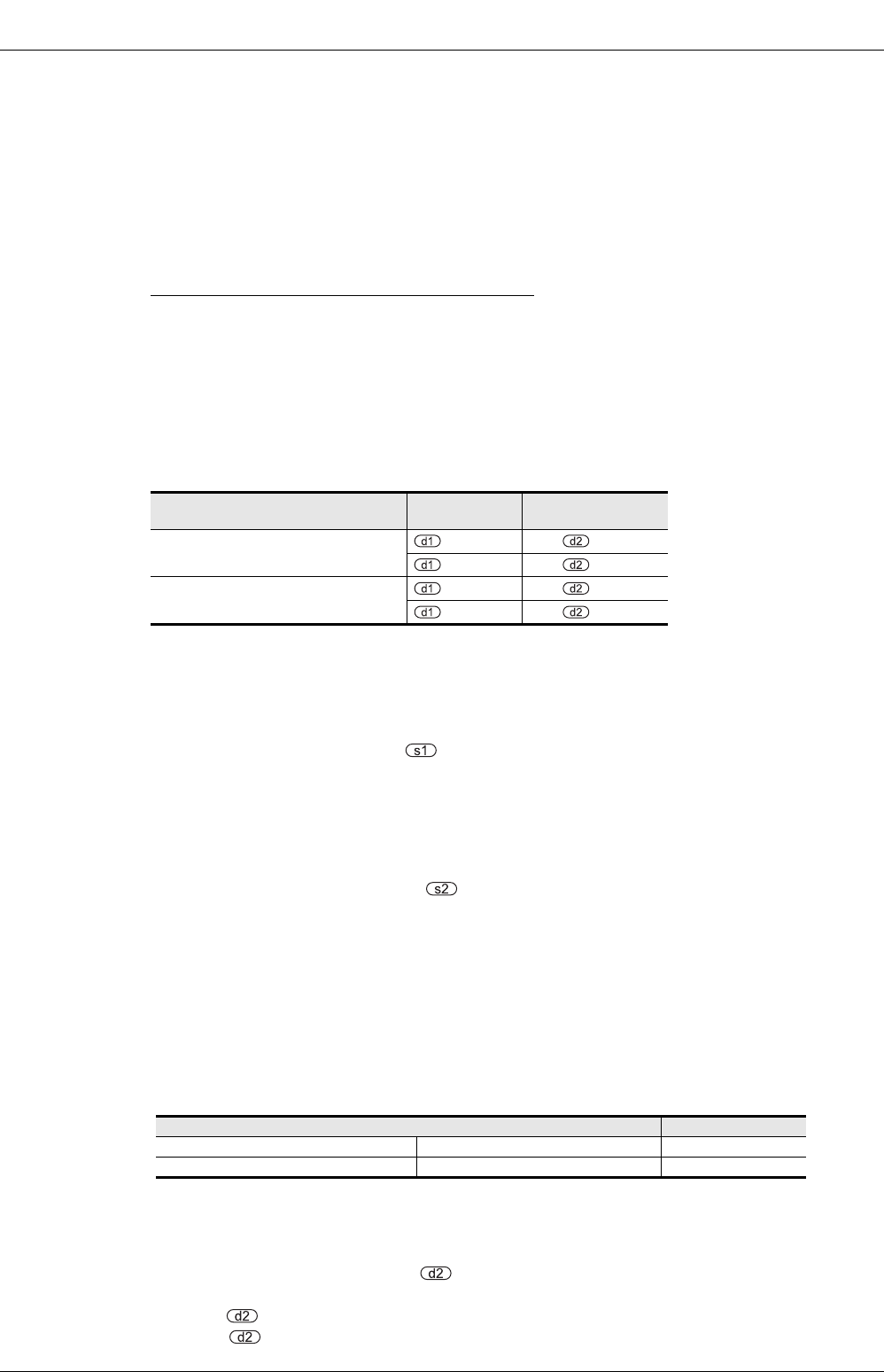
Connection position of high speed
output special adapter
Pulse output
Rotating direction
signal
First unit
=Y000 =Y004
=Y001 =Y005
Second unit
=Y002 =Y006
=Y003 =Y007
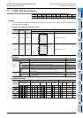
Pulse output destination Setting range
FX3U PLC High speed output special adapter 10 to 200,000 (HZ)
FX3S, FX3G, FX3GC, FX3U, FX3UC PLCs Basic unit (transistor output) 10 to 100,000 (HZ)