


42
3 Configuration of Instruction
3.1 Expression and Operation Form of Sequence Instructions
FXCPU Structured Programming Manual
[Basic & Applied Instruction]
3. Configuration of Instruction
This chapter explains the configuration of sequence instructions.
3.1 Expression and Operation Form of Sequence Instructions
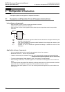
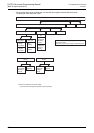
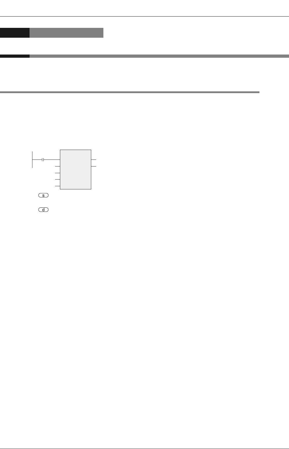
Instructions and arguments
• Each instruction is given a specific name that indicates its contents.
"SMOV" (shift move) is one of such examples.
• Each instruction consists of the arguments that indicate input and output data used in that particular
instruction.
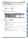
: This symbol indicates an argument called "source" that does not change its contents by the
execution of an instruction.
: This symbol indicates an argument called "destination" that changes its contents by the
execution of an instruction.
m, n : Symbols "m" and "n" indicate an argument that belongs to neither the source nor the
destination.
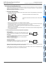
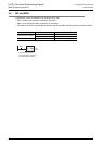
Applicable devices of arguments
• An input variable (label or device) specifies the applicable device of an argument.
• Bit devices such as X, Y, M and S may be handled.
• These bit devices may be combined to form KnX, KnY, KnM and KnS to be handled as numerical data.
→ FX Structured Programming Manual [Device & Common]
• The current value register of data register D, timer T and counter C may be handled.
• When handling 32-bit data, a 16-bit data register D is a combination of data registers of two consecutive
points.
For example, where data register D0 is defined by a label as the argument of a 32-bit instruction, the 32-bit
data of (D1, D0) is handled. (D1 is high order 16 bits and D2 is low order 16 bits.)
Where the current value registers of T and C are used as general data registers, they are handled in the
same manner.
SMOV
EN
s
m1
ENO
d
D10D0
K1
m2
K2
n
K3
Command
input